
Light emitter

A luminous body and polarized light technology, applied in the field of luminous body, can solve the problems of unreasonable light irradiation range, large loss of light energy, glare and other problems of luminous body, and achieve the effect of improving light energy utilization rate and large luminous angle

Active Publication Date: 2013-02-06
FUJIAN HONGBO OPTO ELECTRONICS TECH CO LTD
View PDF12 Cites 1 Cited by
  • Summary
  • Abstract
  • Description
  • Claims
  • Application Information

AI Technical Summary

Problems solved by technology

[0008] The present invention designs a new type of luminous body in order to solve the defects of unreasonable light irradiation range, large loss of light energy and easy glare in the prior art.

Method used


Image

  • Light emitter
  • Light emitter
  • Light emitter

Examples


Embodiment 1

[0036] In this technical solution, the illuminant adopts polarized straw hat lamp beads, and the polarized straw hat lamp beads are arranged on the outer periphery of the carrier in the same way, and the straw hat lamp beads include a bracket 1, an internal reflector 2, and a package lens 3 and LED chips4.

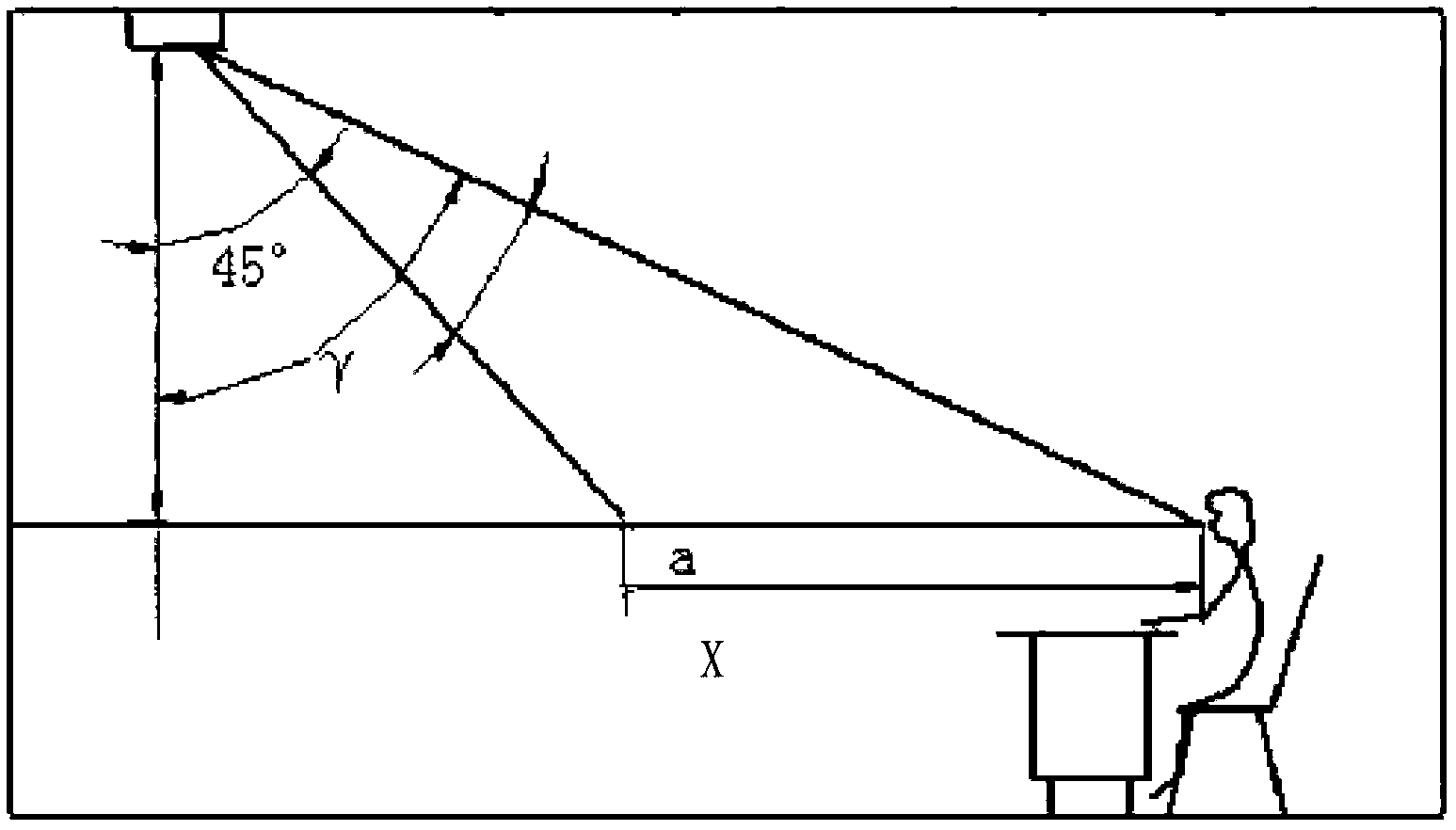
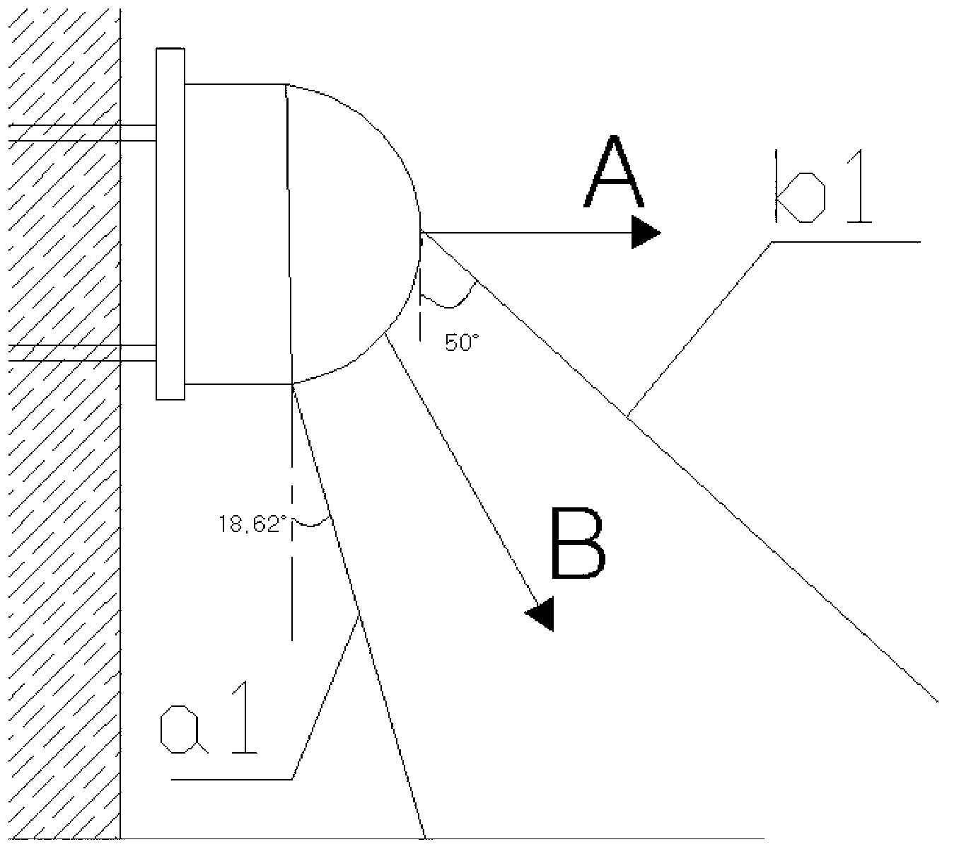
[0037] Further, in order to make the polarized light of the illuminant downward, reduce the waste of light sources, and reduce the glare angle, refer to Figure 7 The specific structure of the straw hat lamp beads used in this technical solution is as follows:

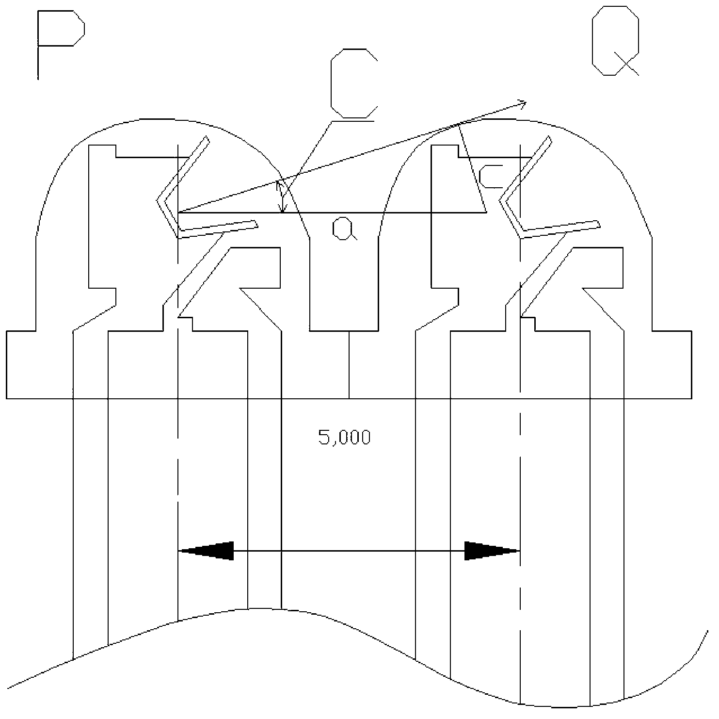
[0038] The internal reflector 2 is a "bowl-shaped" internal reflector 2, the opening diameter of which is larger than the diameter of the bottom, the LED chip 4 is placed at the bottom of the internal reflector 2, and the internal reflector 2 is inclined at a certain angle. On the bracket 1; the packaging lens encapsulates the internal reflector 2 and the LED chip 4; the packaging lens 3 is a C90°-270° asymmetric ...

Embodiment 2

[0044] refer to Figure 9 , different from the above technical solution, the curved surface of the encapsulating lens 3 is asymmetrical at C90°-270°. If the bottom surface of the internal reflector is not inclined, the incident ray 5 will be refracted on the lens surface, instead of being emitted in the direction of the original incident ray 6 , it will become the direction of the refracted ray 7 . The lamp beads of this structure only rely on the asymmetric shape of the lens to change the direction of light emission.

Embodiment 3

[0046] refer to Figure 10 Different from the above technical solution, the bottom surface of the LED chip is inclined, and the direction of the inclination is uncertain. The curved surface of the packaging lens 3 is symmetrical to the central axis of the lamp bead. This structure of the LED lamp bead can rely on the LED chip and the package placed obliquely. The cooperation of the lens 3 obliquely deflects the final light emitting direction.


PUM


Abstract

The invention provides a light emitter which comprises a carrier and a driving power supply which is arranged inside the carrier, wherein beads are installed at the periphery of the carrier; a plurality of rows of beads are uniformly arranged at the periphery of the carrier; and the beads are of polarized light type straw hat beads. By adopting the polarized light type straw hat beads, the light emitter can be combined into a polarized light type LED (light emitting diode) light emitter without an external reflector, but the straw hat beads adopting a polarized light type design and one-time light distribution are used as a light source foundation, full angles of the straw hat beads are controlled as 100 degrees, a lamp shielding angle at one single side is 50 degrees, the polarized light of the light emitter is ejected out downwards in a certain angle, so that direct glare of a lamp is reduced, and a radiation range and brightness of the light emitter are reasonable.

Description

technical field [0001] The invention relates to the technical field of lighting, in particular to a luminous body. Background technique [0002] In the context of the current global energy shortage concerns rising again, the energy issue is an important issue we face in the future. In the field of lighting, the application of LED products is attracting the attention of the world. LED has many advantages such as low power consumption, long service life, energy saving, and environmental protection. It is more and more widely used in various fields. It is a new light source in the 21st century. It has the incomparable advantages of traditional light sources such as high efficiency, fast response time, and not easily damaged. [0003] The LED lamp bead has a large luminous angle. In order to make the lamp suitable for large-scale lighting occasions, the LED lamp bead is usually installed on the main body of the rod-shaped lamp to form a 360° light. Its shape is like a corn cob,...

Claims


Application Information

Patent Timeline
IPC IPC(8): F21S2/00F21V19/00H01L33/60H01L33/58F21Y101/02F21K9/20F21Y115/10
Inventor 黄胜邦罗时睿阮锐陈克昌
Owner FUJIAN HONGBO OPTO ELECTRONICS TECH CO LTD
Learn More