Automatic deashing device for thermal-powered or thermoelectric boilers

An automatic ash cleaning and boiler technology, which is used in the removal of solid residues, lighting and heating equipment, combustion products treatment, etc. Overall coordination, etc.

Inactive Publication Date: 2013-02-06
张自强
View PDF2 Cites 0 Cited by
  • Summary
  • Abstract
  • Description
  • Claims
  • Application Information

AI Technical Summary

Problems solved by technology

[0003] The existing technology only directly connects the air source and the energy starter type components of the basic functional components, and the energy temporary storage and the energy starter type components, without considering the further cooperation between the pipeline and the functional components, and the relationship between the pipeline and the pipeline. The coordination between the pipelines and the coordination of the parameters of each part of the functional components in the entire pipeline system. Therefore, the existing technology generally has poor effects, and the effective range of the radiated shock wave and airflow is very short, often only about 3m, which is far from meeting the needs of large-scale pipelines. , medium-sized boilers to remove ash deposits, especially for the ash deposits in dead angles, leeward sides, and outside the range of the boiler, and there is no way to adjust the radiation shape of the shock wave and airflow, and the intensity decays quickly, etc.
For example, the size of the intake pipe and the guide pipe are matched with each other, the connection of multi-stage pipelines is coordinated with each other, and the cooperation between the inlet and outlet pipelines and the energy temporary storage, and the overall coordination of further regional components and pipelines, and the entire system. The cooperation between pipelines and functional components does not give full play to the advantages of local cooperation and overall cooperation

Method used


Image

  • Automatic deashing device for thermal-powered or thermoelectric boilers
  • Automatic deashing device for thermal-powered or thermoelectric boilers
  • Automatic deashing device for thermal-powered or thermoelectric boilers

Examples


Embodiment Construction

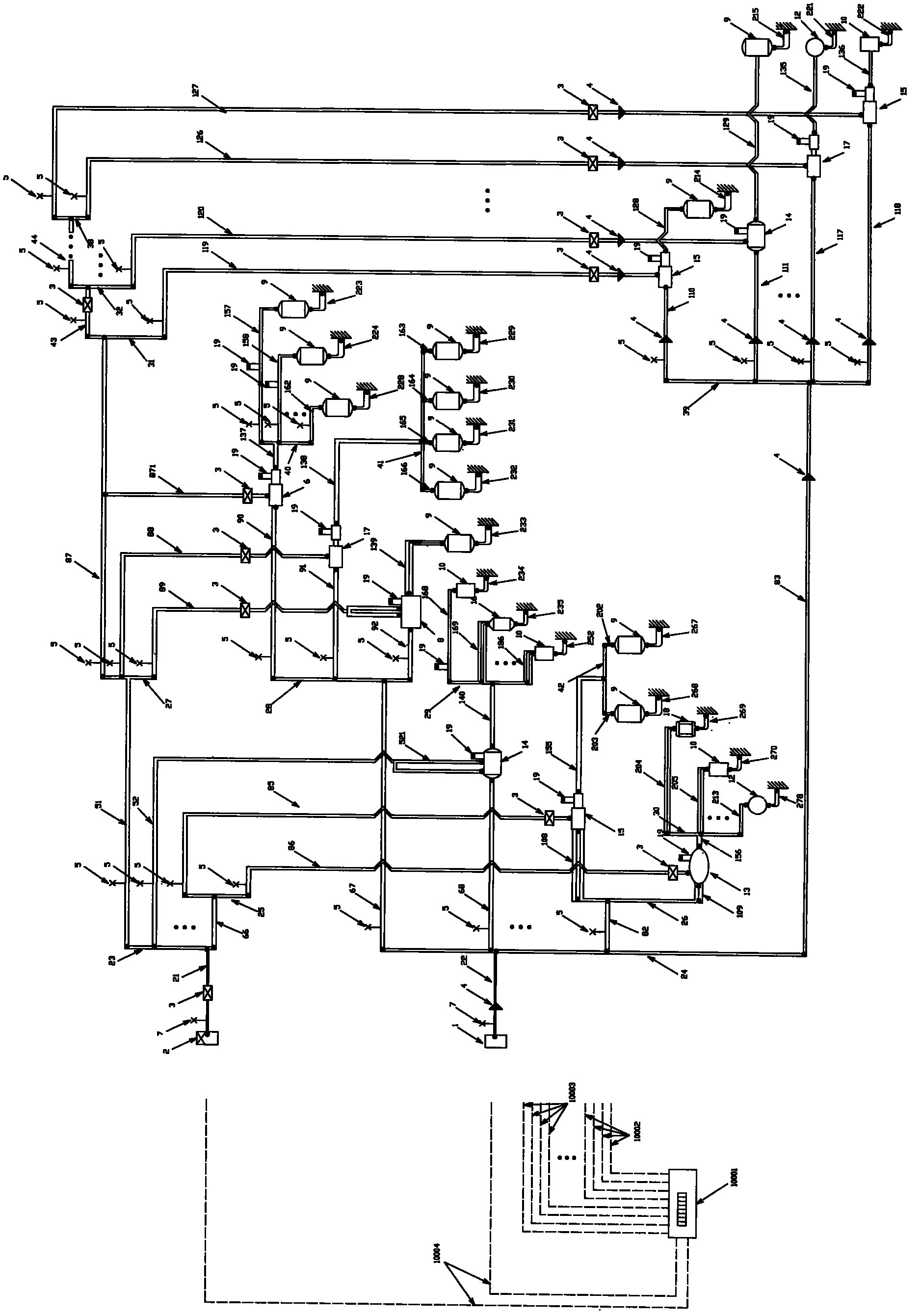
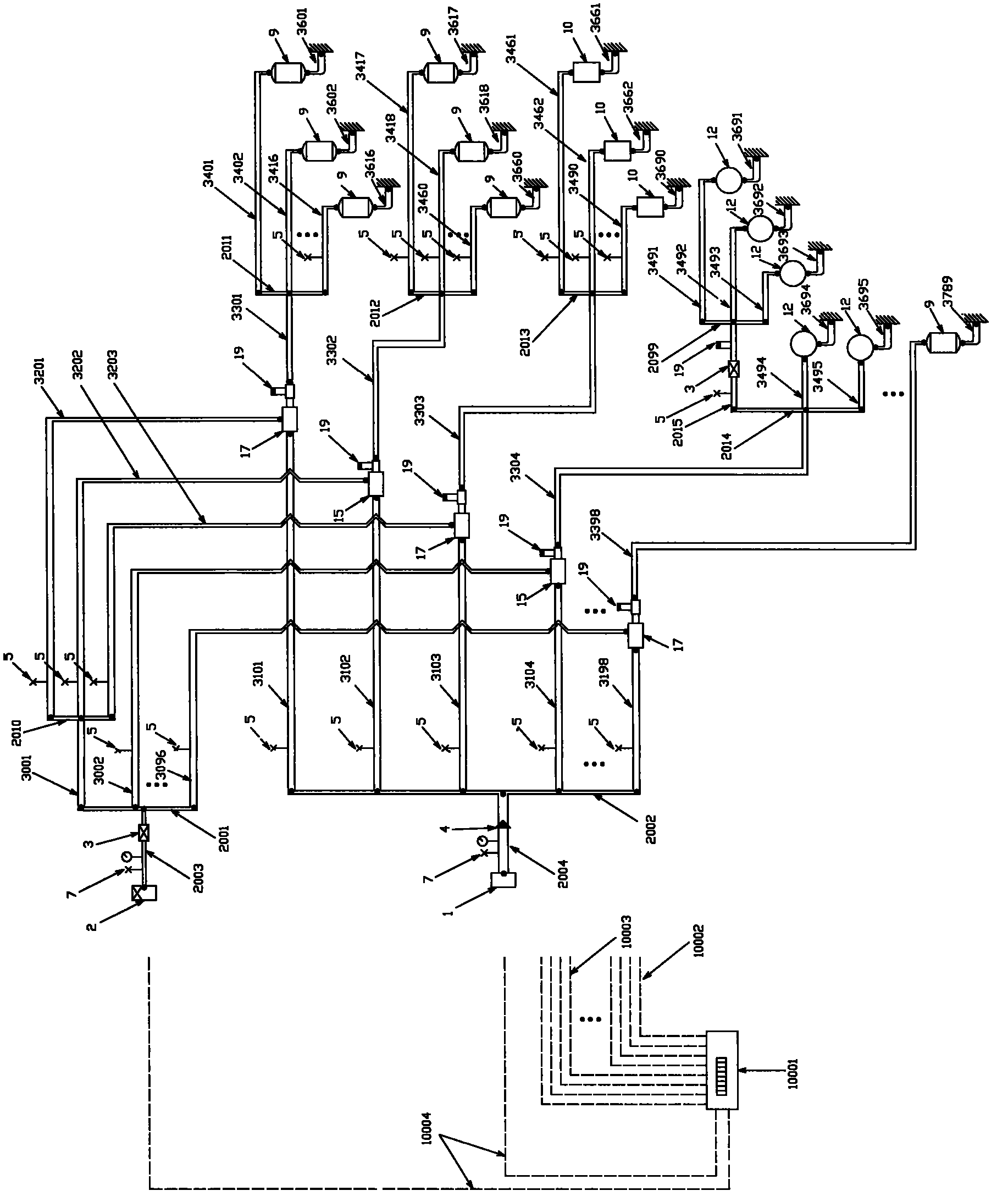
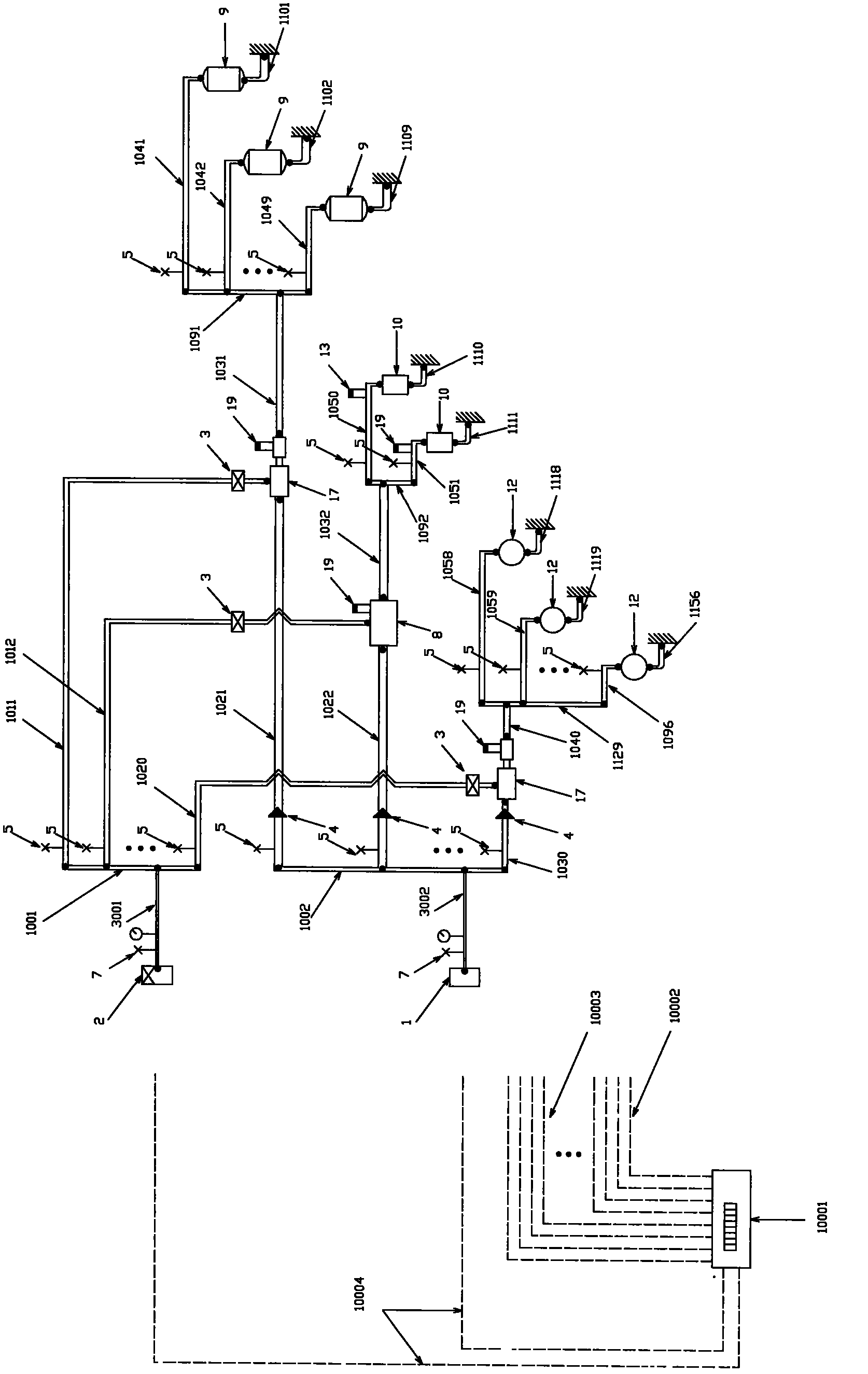
[0030] The system of the present invention consists of a gas source, a main branch converter, an energy starter, an energy temporary storage container, a diversion tube, a blocking component, a connecting pipeline, a control valve, a PLC and a control valve, a control cable, etc. figure 1 connected.

[0031] Such as figure 1As shown, the gas source 2 uses bottled acetylene gas at a certain pressure, and is connected to the main pipeline 21. The steel pipe whose outer diameter ranges from 8mm to 180mm and whose wall thickness ranges from 0.8mm to 45mm is selected, and the main control valve 7 is set. Connect a fire arresting valve 3 according to the conventional fire arresting requirements, and the main pipe 21 is connected to the inlet of the gas collector 23 for the main sub-conversion distribution. The gas collector 23 adopts a square metal tube with a side length of 300mm to 900mm, and the two ends are sealed and welded to form a container 16 holes are opened on the side o...


PUM


Abstract

An automatic deashing device for thermal-powered or thermoelectric boilers sequentially comprises an air source and a gas source, an air path and a gas path, a main and branch converter, an energy starter, energy temporary storage units and a pipeline unit. The air source and the gas source, the air path and the gas path, the main and branch converter, the energy starter and the energy temporary storage units are connected by the pipeline unit, and guide pipes are connected with output ends of the energy temporary storages. The automatic deashing device is characterized in that the pipeline unit comprises multiple pipelines with different parameters, parameters of the pipelines are matched with corresponding parameters of corresponding energy temporary storages, so that minimum detonation energy loss is achieved and shape and intensity distribution of airflow are adjusted; further, the parameters include shape, size, wall thickness, cross-sectional area and volume, the external diameters of the pipelines between the air source and the main and branch converter range from 14 mm(millimeter) to 219 mm, and the external diameters of the pipelines between the gas source and the main and branch converter in the gas path range from 10 mm to 180 mm.

Description

technical field [0001] The invention relates to a device capable of automatically cleaning dust for thermal power generation or thermal power boilers, especially a pipeline system for distribution and transmission after distribution in the main circuit and mixing in the middle branch circuit. [0002] This system is applied to the boiler flue of thermal power and thermal power plant to automatically remove the ash in it, and is installed on the outside of the boiler wall. Background technique [0003] The existing technology only directly connects the air source and the energy starter type components of the basic functional components, and the energy temporary storage and the energy starter type components, without considering the further cooperation between the pipeline and the functional components, and the relationship between the pipeline and the pipeline. The coordination between the pipelines and the coordination of the parameters of each part of the functional compone...

Claims


Application Information

Patent Timeline
Patent Type & Authority Applications(China)
IPC IPC(8): F23J1/00F23J3/00
Inventor 邱小琼
Owner 张自强
Why Eureka
Try Eureka