
Spring-lever energy storage type fatigue tension test machine

A technology of tensile testing machine and testing machine, which is applied in the direction of measuring devices, instruments, scientific instruments, etc., can solve the problems of expensive equipment and high cost of experiments, and achieve the goal of reducing impact, reducing vibration and impact, and reducing costs Effect

Inactive Publication Date: 2013-02-06
BEIJING INSTITUTE OF TECHNOLOGYGY
View PDF4 Cites 23 Cited by
  • Summary
  • Abstract
  • Description
  • Claims
  • Application Information

AI Technical Summary

Problems solved by technology

At present, there are more common electromagnetic tensile testing machines and hydraulic tensile testing machines. The former uses the principle of electromagnetic resonance to achieve periodic tensile loads and requires electromagnetic conversion devices; the latter uses the principle of hydraulic pulsating loads to achieve predetermined pulsating tension. , it is necessary to design hydraulic pipelines and solve problems such as sealing; the above two kinds of equipment have complete functions, and the equipment price is relatively expensive, and are mostly used for fatigue tests strictly in accordance with industrial specifications, and the cost of the experiment is relatively high; in many cases, it is only for Prefabricating fatigue cracks in materials or studying some physical effect changes of crack propagation under dynamic loads does not require strict calibration of material fatigue characteristics. For this reason, simple and small equipment is often used to meet the experimental requirements without much investment.

Method used

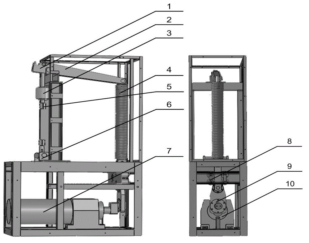

Image

  • Spring-lever energy storage type fatigue tension test machine
  • Spring-lever energy storage type fatigue tension test machine
  • Spring-lever energy storage type fatigue tension test machine

Examples


Embodiment Construction

[0013] In order to better illustrate the purpose and advantages of the present invention, the present invention will be further described below in conjunction with the accompanying drawings and specific embodiments.

[0014] In the embodiment, the 16MnR material commonly used in the pressure vessel is used to make the tensile test piece. The effective width of the test piece is 26mm, and the thickness of the test piece is 4mm. The main structural dimensions of the test piece figure 2 shown.

[0015] Implementation process: 1. First, pull out the fixing screws of the upper and lower stretching heads 5 and 6 of the stretching machine, and when the specimen is aligned with the upper and lower stretching heads, insert the fixing screws into it. At this time, the specimen has been fixed on the stretching machine. 2. Turn on the power switch, and the power indicator light will be on. 3. Set the pre-tightening force to 10000N by adjusting the base nut, and the pre-tightening force...


PUM


Abstract

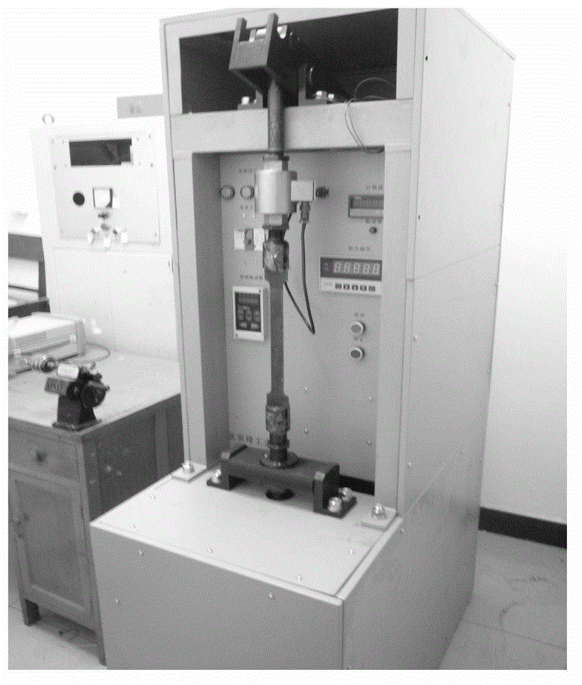
The invention relates to a novel mechanical structure design scheme, which is used for testing test pieces made of various metal and alloy materials at room temperature and bearing tension fatigue characteristic, fatigue life and fatigue crack expansion test of mechanical parts (such as various mechanical connecting pieces). According to the scheme, a motor drives a speed reducer to rotate, the spring is subjected to energy storage by an eccentric shaft coupler and a crank connecting rod mechanism, the spring is controlled by four guide wheels to do vertical reciprocating motion, the potential energy of the spring is converted into moment through a lever, and extension and compression of the spring are reinforced by a lever mechanism, so that tension bars are separated vertically and the stretching effect is achieved; and force amplitude is changed through connecting points at different positions of the lever, so that fatigue tension tests of different frequency and different amplitude are realized. The invention is simple in structure and low in manufacturing cost, adopts a mechanical structure, can meet the basic performance requirement of the fatigue tension test, and can be applied to the tensile fatigue test under the lab environment.

Description

technical field [0001] The invention relates to a design of a simple testing machine for performing material fatigue tensile tests in a laboratory environment, which can realize fatigue tests of tensile test pieces under the action of different frequencies and load values ​​within a certain range, and provides materials for fatigue tests in materials science A simple and convenient solution. Background technique [0002] Fatigue tensile testing machine is a machine mainly used to determine the fatigue performance of metal or alloy materials when they are subjected to cyclic tensile loads. At present, there are more common electromagnetic tensile testing machines and hydraulic tensile testing machines. The former uses the principle of electromagnetic resonance to achieve periodic tensile loads and requires electromagnetic conversion devices; the latter uses the principle of hydraulic pulsating loads to achieve predetermined pulsating tension. , it is necessary to design hydr...

Claims


Application Information

Patent Timeline
IPC IPC(8): G01N3/34G01N3/02
Inventor 张卫民徐春广于霞邱勇王书浩
Owner BEIJING INSTITUTE OF TECHNOLOGYGY
Learn More