
Method and device for measuring parameter of asynchronous motor

A technology of asynchronous motor and measurement method, which is applied in the direction of motor generator testing, etc., and can solve the problem of low accuracy of rotor time constant

Inactive Publication Date: 2013-02-06
SHENZHEN HANGSHENG ELECTRONICS
View PDF5 Cites 8 Cited by
  • Summary
  • Abstract
  • Description
  • Claims
  • Application Information

AI Technical Summary

Problems solved by technology

[0005] The technical problem to be solved by the present invention is to provide a method and device for measuring the parameters of an asynchronous motor with a relatively high precision of the measured rotor time constant, aiming at the defects of the prior art that the measured rotor time constant is not high in accuracy

Method used


Image

  • Method and device for measuring parameter of asynchronous motor
  • Method and device for measuring parameter of asynchronous motor
  • Method and device for measuring parameter of asynchronous motor

Examples


Embodiment Construction

[0056] In order to facilitate those of ordinary skill in the art to understand and implement the present invention, the embodiments of the present invention will be further described below in conjunction with the accompanying drawings.

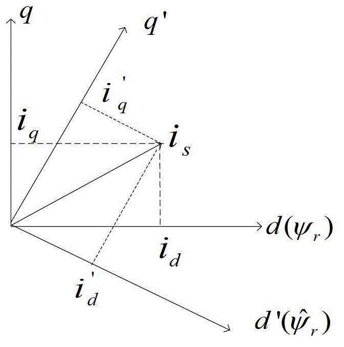
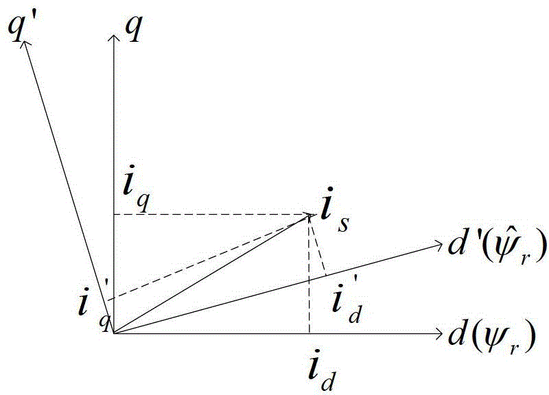
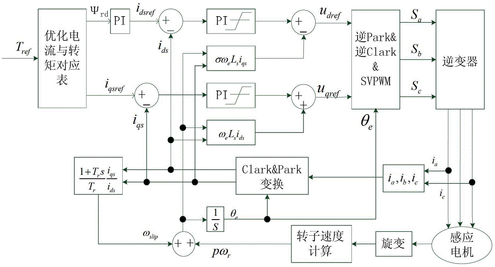
[0057] figure 1 is the rotor flux linkage and current decoupling position map when the actual rotor time constant is less than its set value, figure 2 is the rotor flux linkage and current decoupling position map when the actual rotor time constant is greater than its set value, image 3 Is the control block diagram of the vector control system.

[0058] In the measurement method and device embodiment of the asynchronous motor parameters of the present invention, the flow chart of the measurement method is as follows Figure 4 As shown, the method includes the following steps:

[0059] Step S11 presets the reference excitation current and the reference torque current, and sets the first rotor time constant and the second rotor time constan...


PUM


Abstract

The invention relates to a method for measuring a parameter of an asynchronous motor. The method comprises the following steps of: presetting a reference exciting current and a reference torque current, setting a first rotor time constant and a second rotor time constant; obtaining a first slip frequency and a second slip frequency which respectively correspond to the first rotor time constant and the second rotor time constant by using a slip frequency formula; respectively obtaining a first output torque and a second output torque which correspond to the first rotor time constant and the second rotor time constant; and respectively substituting the first output torque, the second output torque, the first slip frequency and the second slip frequency into a torque formula to work out an actual rotor time constant, wherein an output torque in the torque formula is a product of a first coefficient and an expression including the rotor time constants and the slip frequency product. The invention also relates to a method for realizing the device. The method and device for measuring the parameter of the asynchronous motor have the beneficial effect that the measured rotor time constant is high in accuracy.

Description

technical field [0001] The invention relates to the field of electric vehicles, in particular to a method and device for measuring parameters of an asynchronous motor. Background technique [0002] As a high-performance asynchronous motor control technology, vector control is being more and more widely used in various occasions. Generally speaking, motor parameters need to be measured before vector control. For vector control of asynchronous motors, the accuracy of asynchronous motor parameters has a great influence on its control performance, especially the rotor time constant. The accuracy of the rotor time constant directly affects the decoupling effect of the vector control. When the accuracy of the rotor time constant is poor, there will be errors in the orientation of the magnetic field, resulting in a decrease in the performance of the control system. For electric vehicles, the control of the traction motor will choose vector control as the basic algorithm, and the ...

Claims


Application Information

Patent Timeline
IPC IPC(8): G01R31/34
Inventor 姚伟科刘爱华郑春阳
Owner SHENZHEN HANGSHENG ELECTRONICS
Learn More