Zigzag waveguide slow-wave line

A meandering waveguide and slow wave line technology, applied in the field of microwave vacuum electronic devices, can solve the problem of narrow operating frequency band

Inactive Publication Date: 2013-02-06
UNIV OF ELECTRONIC SCI & TECH OF CHINA
View PDF8 Cites 7 Cited by
  • Summary
  • Abstract
  • Description
  • Claims
  • Application Information

AI Technical Summary

Problems solved by technology

However, the working frequency band is narrow, and

Method used


Image

  • Zigzag waveguide slow-wave line
  • Zigzag waveguide slow-wave line
  • Zigzag waveguide slow-wave line

Examples


Embodiment Construction

[0026] Specific embodiments of the present invention will be described below in conjunction with the accompanying drawings, so that those skilled in the art can better understand the present invention. It should be noted that in the following description, when detailed descriptions of known functions and designs may dilute the main content of the present invention, these descriptions will be omitted here.

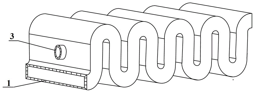
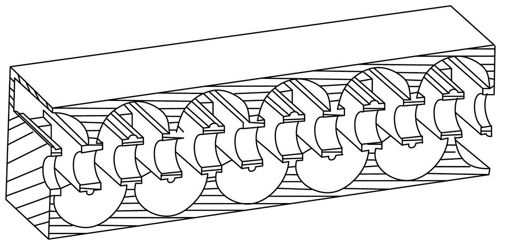
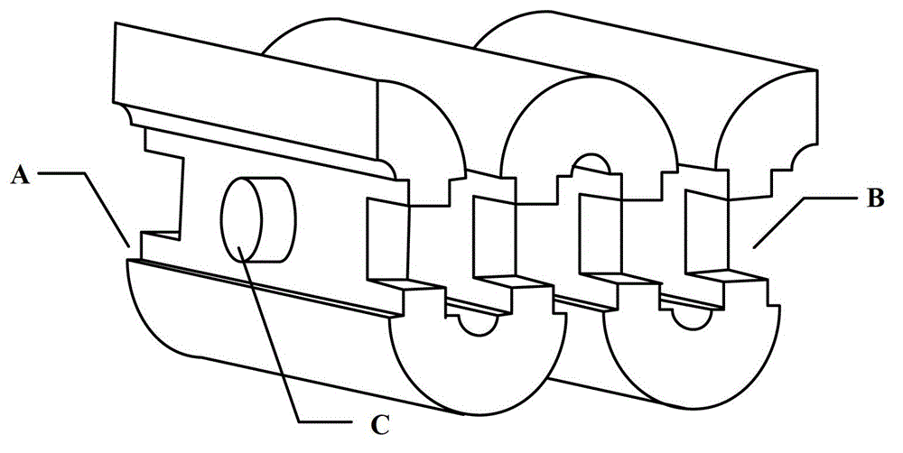
[0027] In this example, if Figure 1~5 As shown, the meander waveguide is formed by connecting a series of arc-curved waveguides and straight waveguides end-to-end. Of course, in a specific implementation process, it is also possible to use a right-angle curved waveguide and a straight waveguide connected end-to-end. The meandering waveguide is equivalent to the meandering waveguide structure formed by periodically bending the rectangular waveguide 1 into a U-shaped meandering line (or a right-angled meandering line) along the electric field surface. Metal ridges 4 of a c...


PUM


Abstract

The invention discloses a zigzag waveguide slow-wave line which comprises a zigzag waveguide and a plurality of metal ridge pieces and metal wing pieces, wherein the zigzag waveguide is formed by connecting a series of arc bending waveguides or right-angled bending waveguides and straight waveguides end to end; and one metal ridge piece in a certain thickness is loaded along the wide side direction of the internal wall of each of the straight waveguides, and one metal wing piece in a certain thickness is loaded along the narrow side direction of the internal wall of each of the straight waveguides. Circular through holes are arranged on the internal wall of the wide side of the straight wave guide and the metal ridge piece along the axial symmetry line of the zigzag waveguide, and the circular through holes of the straight waveguides of the two adjacent zigzag units are connected by a metal tube in the same aperture size of the circular through hole so as to form an electronic stream channel. The test indicates that the zigzag waveguide slow-wave line has a more flat dispersion curve in the same structural size, so that the zigzag waveguide slow-wave line can work in a wider scope of frequency band, with a wider working frequency band, and in addition, the coupled impedance can be increased.

Description

technical field [0001] The invention belongs to the technical field of microwave vacuum electronic devices, and more specifically relates to a beam-wave interaction device of a traveling wave tube: a meander wavelength slow wave line. Background technique [0002] As the most widely used electric vacuum device in the microwave frequency band, the traveling wave tube has a prominent application status in many fields such as millimeter wave radar, communication, microwave remote sensing, and radiation measurement. The slow wave structure (slow wave line) is the core component of the beam-wave interaction of the traveling wave tube, and its performance directly determines the technical level of the traveling wave tube. [0003] At present, there is a serious contradiction between the output power and the working bandwidth of the traveling wave tube. The helical slow wave line and its deformed slow wave line traveling wave tube have a very wide bandwidth, but the output power i...

Claims


Application Information

Patent Timeline
IPC IPC(8): H01J23/24
Inventor 侯艳宫玉彬王少萌徐进魏彦玉
Owner UNIV OF ELECTRONIC SCI & TECH OF CHINA
Why Eureka
Try Eureka