Wireless camera

A wireless camera and camera technology, applied in the information field, can solve the problems of inconvenience, inconvenient device connection, miniaturization of the camera and difficulty in taking into account the imaging quality, etc.

Inactive Publication Date: 2013-02-06
WUXI CHENGDIAN KEDA TECH DEV
View PDF9 Cites 1 Cited by
  • Summary
  • Abstract
  • Description
  • Claims
  • Application Information

AI Technical Summary

Problems solved by technology

There are many problems in the structure and use of the camera connected by the above connection relationship. First, there must be a connection line between the above-mentioned existing camera and the image display terminal. Therefore, there is a certain distance between the camera and the display terminal when connecting the equipment. It is very inconvenient to carry out the above-mentioned device connection; secondly, the existing display terminal is one of the PC display or monitor; moreover, in the prior art, a display terminal can only monitor images from one camera
[0003] It can be seen that the above-mentioned existing cameras obviously still have inconvenience and defects in structure and use, and need to be further improved urgently.
[0004] In addition, the cameras in the prior art generally have the shortcomings and defects that it is difficult to balance the miniaturization of the volume and the imaging quality.

Method used


Image

  • Wireless camera
  • Wireless camera
  • Wireless camera

Examples


Embodiment Construction

[0018] In order to make the technical means, creative features, goals and effects achieved by the present invention easy to understand, the present invention will be further described below in conjunction with specific illustrations.

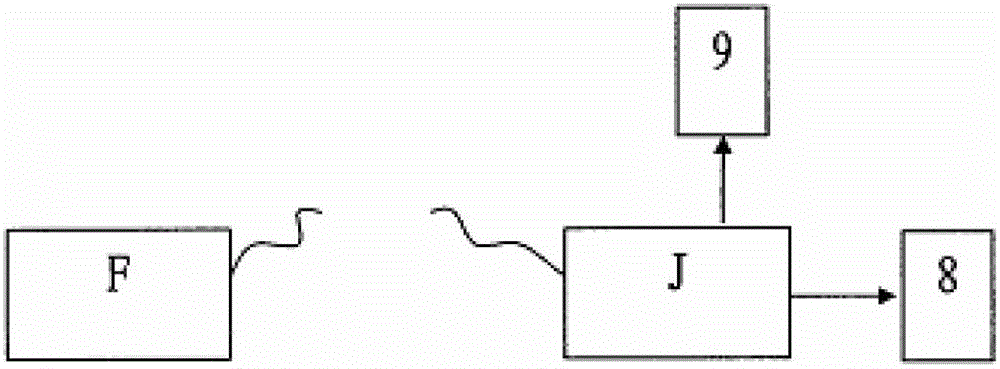
[0019] figure 1 Shown is the principle diagram of the wireless camera of the present invention, which includes: being set on one side of the position to be monitored, receiving and processing the image and sound signals of the position to be monitored, and transmitting the processed signal by wireless signal The transmitter F; and the receiving terminal J that receives and processes the signal transmitted by the transmitter F, and transmits the received and processed signal to a TV and / or PC for display and output of video and audio signals.

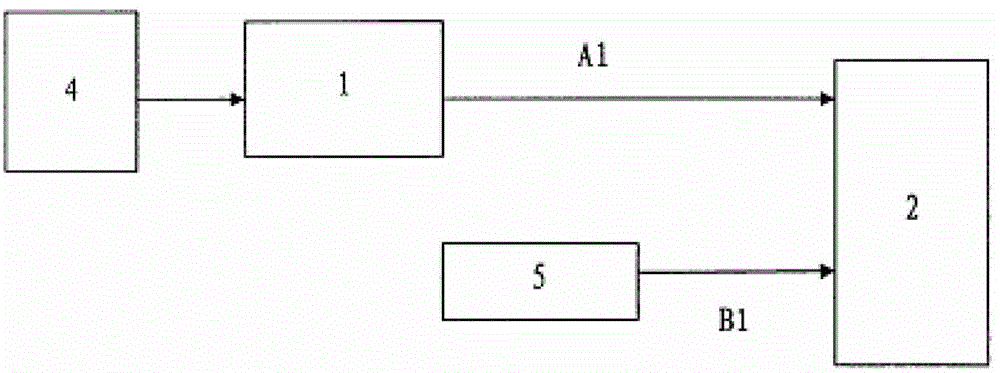
[0020] see figure 2 Shown is the schematic diagram of the transmitting end of the wireless camera of the present invention, and the transmitting end F of the present invention includes: a camera 4 that s...


PUM


Abstract

The invention discloses a wireless camera, and comprises a transmitting end and a receiving end, wherein the transmitting end comprises a video processing module, a signal transmitting moudle, a camera and an audio input device. The transmitting end is characterized in that the camera only contains three lenses with flexion force; a first convex lens with a focal length f1, a second double-concave lens with a focal length of f2, a third double-convex lens with a focal length of f2, and an image sensor for undertaking an image are sequentially arranged from the object side to the image side; the ratio of f1 to f2 is minus 0.2 to minus 1.5, and the ratio of f1 to f3 is 0.45 to 1.33; the distance d1 between the first convex lens and the second double-concave lens is 2-8mm; and the surfaces at the image sides of the third double-convex lens and the second double-concave lens are respectively provided with a binary optical structure for further eliminating imaging aberration.

Description

technical field [0001] The invention relates to the field of information technology, in particular to a wireless camera. Background technique [0002] Along with the development of society camera is more and more popularized in the application of each field, yet, the camera of prior art all is directly connected on the computer (hereinafter all referred to as PC) machine with universal serial bus (hereinafter all referred to as USB) line . There are many problems in the structure and use of the camera connected by the above connection relationship. First, there must be a connection line between the above-mentioned existing camera and the image display terminal. Therefore, there is a certain distance between the camera and the display terminal when connecting the equipment. It is very inconvenient to carry out the above-mentioned equipment connection; secondly, the existing display terminal is one of the PC display or monitor; moreover, in the prior art, a display terminal c...

Claims


Application Information

Patent Timeline
IPC IPC(8): H04N5/225H04N7/18G03B17/12G02B13/18G02B13/00
Inventor 吴跃吴双吴少智周益民
Owner WUXI CHENGDIAN KEDA TECH DEV
Why Eureka
Try Eureka