Central clutch release means

A clutch and separator technology, applied in clutches, fluid-driven clutches, non-mechanical-driven clutches, etc., can solve problems such as sensor device failure

Inactive Publication Date: 2013-02-06
SCHAEFFLER TECH AG & CO KG
View PDF6 Cites 10 Cited by
  • Summary
  • Abstract
  • Description
  • Claims
  • Application Information

AI Technical Summary

Problems solved by technology

To date, complete failure of the sensing dev...

Method used


Image

  • Central clutch release means
  • Central clutch release means
  • Central clutch release means

Examples


Embodiment Construction

[0027] The drawings are only for the understanding of the invention and are of a schematic nature only. The same elements are denoted by the same reference numerals.

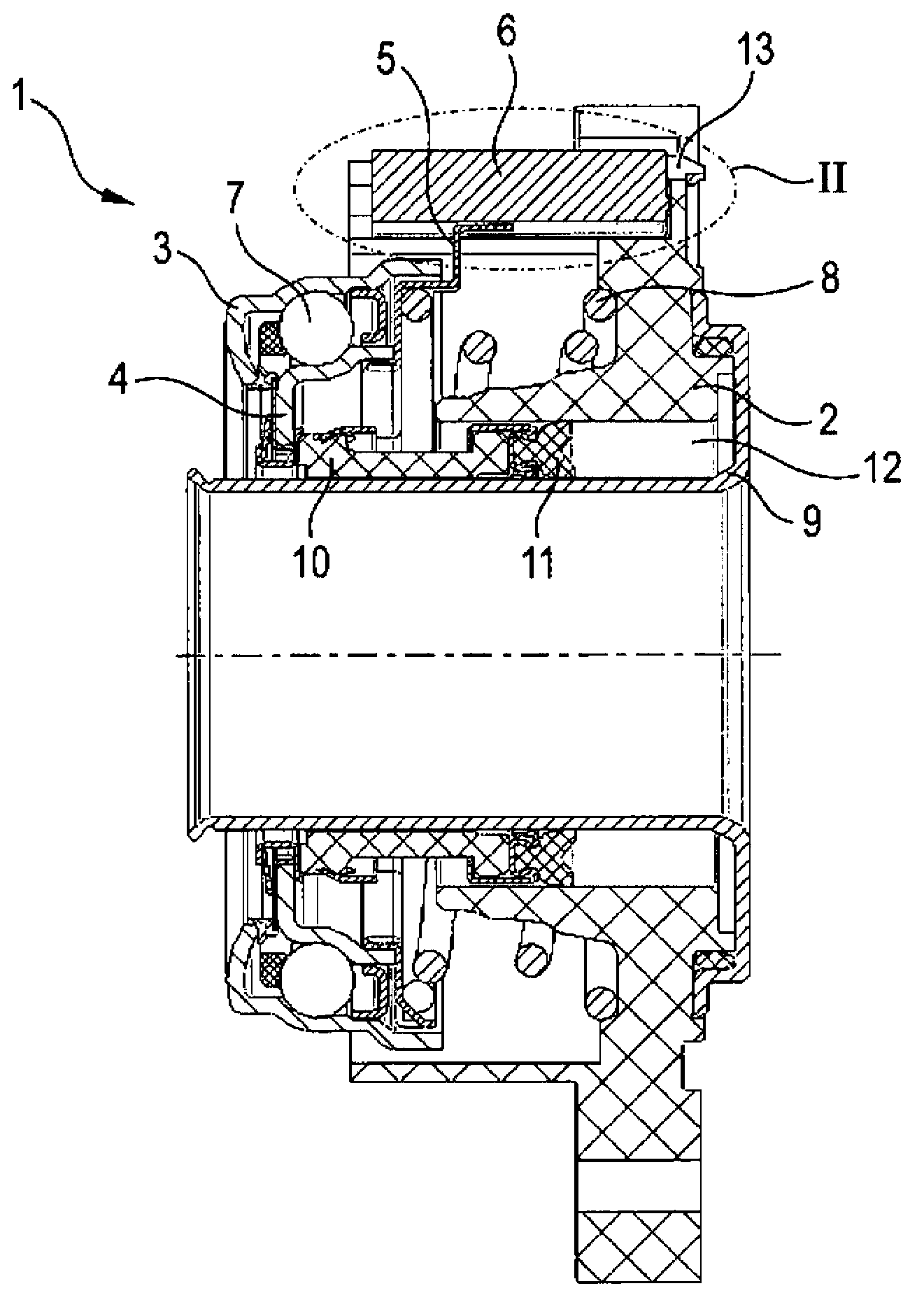
[0028] exist figure 1 A first embodiment of the clutch center release 1 of the invention is shown in . The clutch central separator 1 is also called a central slave cylinder (English: Concentric Slave Cylinder—CSC). The actual housing is provided with the reference numeral 2 . The bearing inner ring 4 of the release bearing connected to the piston 10 is used to actuate the clutch assembly, in particular to make contact with the clutch disc tongues. The bearing outer ring 3 is arranged adjacent to the bearing inner ring 4, which together with the balls located therebetween constitute a release bearing. The position of the preload spring abutment ring 5 and thus of the piston 10 connected to this preload spring abutment ring via the bearing inner ring 4 is sensed by the sensor 6 .

[0029] For the rotation-in...


PUM


Abstract

The invention relates to a central clutch release means, comprising: a housing; a piston which serves to actuate a clutch assembly, is guided axially movably in the said housing and is connected to the inner ring of a disengagement bearing; and a preloading spring bearing ring which is in operative contact with the inner ring, wherein the common unit comprising piston, preloading spring bearing ring and inner ring is arranged such that it can be moved translatorily relative to the housing, and at least the preloading spring bearing ring comprises a material which disrupts magnetic fields, wherein a sensor is attached to the housing in order to sense the position of the preloading ring bearing ring, wherein the preloading spring bearing ring is lengthened axially to such an extent that it is in immediate operative connection with the sensor during the axial displacement of the piston over the entire distance of the latter.

Description

technical field [0001] The invention relates to a clutch central release, comprising: a housing; a piston for actuating a clutch unit, the piston being guided axially movable therein and connected to an inner ring of a release bearing; a a preloaded spring bearing ring in operative contact with the inner ring of the release bearing, wherein the combination of piston, preloaded spring bearing ring and inner ring is arranged movable in translation relative to the housing and At least the preload spring bearing ring comprises a magnetic field disruptive material, wherein a sensor fastened to the housing is also provided in such a way that the sensor determines the position of the preload spring bearing ring and thus at least indirectly accurately determine the position of the piston. Background technique [0002] Clutch center separators are used in the automotive sector to actuate clutch assemblies. [0003] It is desirable to know the exact position of the bearing outer rin...

Claims


Application Information

Patent Timeline
IPC IPC(8): F16D25/08
CPCF16D25/083F16D2300/18
Inventor Y·施密特J·奥斯特
Owner SCHAEFFLER TECH AG & CO KG
Why Eureka
Try Eureka