Radiographic system

A shooting device and radiation technology, which is applied in the direction of measuring devices, radiological diagnosis data transmission, and instruments for radiological diagnosis, etc., which can solve the problems of low image sharpness

Inactive Publication Date: 2013-02-06
FUJIFILM CORP
View PDF8 Cites 2 Cited by
  • Summary
  • Abstract
  • Description
  • Claims
  • Application Information

AI Technical Summary

Problems solved by technology

But the thicker the scintillator, the further away the light from the scintillator is from the substrate, so the sharpness of the resulting image becomes less

Method used


Image

  • Radiographic system
  • Radiographic system
  • Radiographic system

Examples


Embodiment Construction

[0056] Hereinafter, modes for implementing the present invention will be described with reference to the drawings.

[0057] First, the configuration of the radiation detector 20 of the indirect conversion method according to the present embodiment will be described.

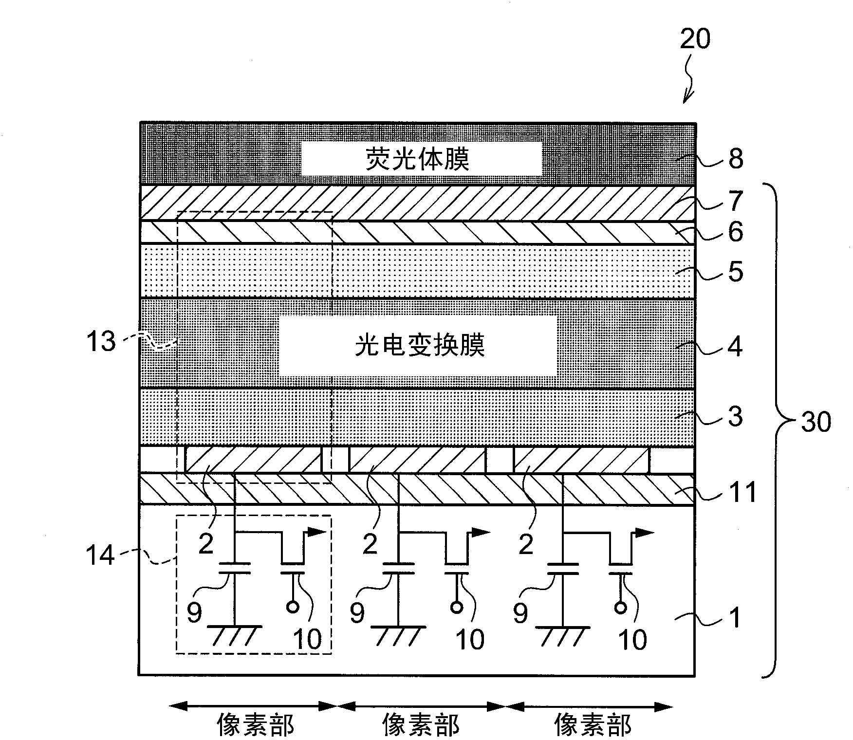
[0058] figure 1 It is a schematic cross-sectional view schematically showing the configuration of three pixel portions of the radiation detector 20 according to one embodiment of the present invention.

[0059] In this radiation detector 20 , a signal output unit 14 , a sensor unit 13 , and a scintillator 8 are sequentially stacked on an insulating substrate 1 . A pixel unit is constituted by the signal output unit 14 and the sensor unit 13 . A plurality of pixel units are arranged on the substrate 1 , and are configured such that the signal output unit 14 and the sensor unit 13 in each pixel unit overlap.

[0060] The scintillator 8 is formed on the sensor unit 13 with the transparent insulating film 7 interp...


PUM


Abstract

A radiographic system comprises two radiation detectors (20 (20A, 20B)) that capture radiological images. Image information representing the radiological images taken by the radiation detectors (20A, 20B) can be individually read, and each sensor unit (13) constituting at least one of the radiation detectors (20) is configured to include an organic photoelectric conversion material that generates an electric charge by receiving light. The radiographic equipment is thus able to capture a variety of radiological images.

Description

technical field [0001] The present invention relates to a radiation imaging device. Background technique [0002] In recent years, radiation detectors such as FPDs (Flat Panel Detectors) capable of directly converting radiation such as X-rays into digital data by disposing a radiation sensitive layer on a TFT (Thin Film Transistor) active matrix substrate have been put into practical use. Compared with the conventional radiographic apparatus using X-ray film or imaging plate, the radiographic apparatus using this radiation detector has fluoroscopic imaging ( Advantages of moving image shooting). [0003] As such radiation detectors, various types have been proposed. For example, there is an indirect conversion method in which radiation is first converted into light by a scintillator such as CsI:Tl or GOS (Gd2O2S:Tb), and then the converted light is converted into electric charge by a sensor such as a photodiode and stored. The radiation imaging apparatus reads the electri...

Claims


Application Information

Patent Timeline
Patent Type & Authority Applications(China)
IPC IPC(8): G01T1/20A61B6/00G03B42/02G03B42/04
CPCA61B6/4208A61B6/4266G01T1/2006A61B6/4241G01T1/20A61B6/4283A61B6/4216A61B6/56
Inventor 中津川晴康西纳直行大田恭义
Owner FUJIFILM CORP
Why Eureka
Try Eureka