H-shaped steel rolling equipment and method

A rolling equipment, H-beam technology, applied in metal rolling and other directions, can solve the problem of high cost of H-beam rolling

Active Publication Date: 2013-02-13
LAIWU IRON & STEEL GRP
View PDF8 Cites 6 Cited by
  • Summary
  • Abstract
  • Description
  • Claims
  • Application Information

AI Technical Summary

Problems solved by technology

[0006] The purpose of the present invention is to provide a low-cost H-shaped steel rolling equipment and method to solve the problem of high cost of existing H-shaped steel rolling

Method used


Image

  • H-shaped steel rolling equipment and method
  • H-shaped steel rolling equipment and method
  • H-shaped steel rolling equipment and method

Examples


Embodiment Construction

[0020] The present invention will be described in further detail below in conjunction with the accompanying drawings and specific embodiments.

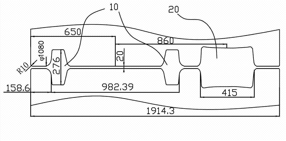
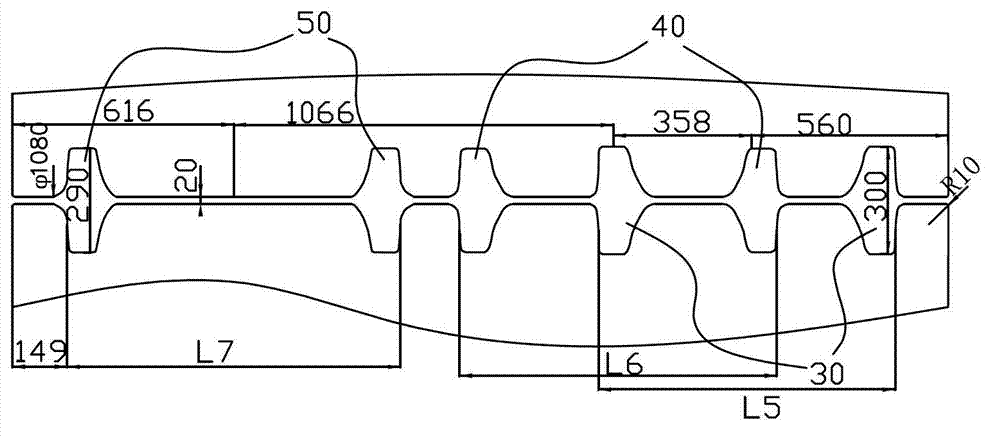
[0021] The invention provides a low-cost H-shaped steel rolling equipment. Like the prior art, the equipment includes a blanking mill and a finishing mill. The billet rolling mill has a variety of rolling passes. Such as image 3 As shown, the multiple rolling passes of the blooming mill in the embodiment of the present invention include a first horizontal rolling pass 30 , a second horizontal rolling pass 40 and a third horizontal rolling pass 50 .

[0022] The lengths between the outer sides of the first horizontal rolling pass 30 , the second horizontal rolling pass 40 and the third horizontal rolling pass 50 increase sequentially, that is, the lengths L5 , L6 , and L7 increase sequentially. In addition, the rolling center lines of the pass types 30, 40, and 50 are exactly the same.

[0023] In this embodiment, the first horizon...


PUM


Abstract

The invention provides H-shaped steel rolling equipment and a method. The equipment comprises a cogging mill and a finishing mill group, wherein the finishing mill group comprises a middle universal mill, an edging mill and a universal finishing mill which are arranged in sequence, and the cogging mill is provided with a plurality of rolling hole patterns. The H-shaped steel rolling equipment and the method are characterized in that the plurality of rolling hole patterns comprise a first horizontal rolling hole pattern, a second horizontal rolling hole pattern and a third horizontal rolling hole pattern, wherein lengths between outsides of hole patterns of the first horizontal rolling hole pattern, the second horizontal rolling hole pattern and the third horizontal rolling hole pattern are increased in sequence. Due to the fact that the cogging mill comprising the plurality of horizontal rolling hole patterns is arranged, the cogging run pass is decreased, and additionally the run pass of the finishing mill group is decreased, and thus the H-shaped steel rolling equipment and the method can greatly decrease the run pass and reduce the cost.

Description

technical field [0001] The invention relates to a section steel rolling equipment, in particular to an H-section steel rolling equipment and method, and belongs to the technical field of metal plastic processing and forming. Background technique [0002] As a kind of economical section steel, H-beam has the advantages of large section modulus, strong bending resistance, light unit weight, beautiful appearance, convenient structure, saving man-hours, reducing engineering cost and being recyclable compared with ordinary I-beam. , has been widely used in structural components such as beams or columns in steel structures of industrial and civil buildings, steel structure load-bearing supports of industrial structures, industrial equipment structures such as petrochemical and electric power, long-span steel bridge components, machinery, vehicles, ships, etc. In engineering structures such as frame structures, underground railways and viaduct components. In recent years, as the d...

Claims


Application Information

Patent Timeline
Patent Type & Authority Applications(China)
IPC IPC(8): B21B1/088
Inventor 孙会朝马新孙庆亮孙翠华刘超吕霞李向荣
Owner LAIWU IRON & STEEL GRP
Why Eureka
Try Eureka