
Molding method for trailing arm beam of rear axle bracket assembly of automobile

A bracket assembly and forming method technology, applied in the direction of forming tools, perforating tools, feeding devices, etc., can solve the problems of unsatisfactory mass production, difficult quality assurance, and low production efficiency, so as to save laser equipment and production The effect of low cost and high production efficiency

Inactive Publication Date: 2013-02-13
柳州市昌河模具厂 +1
View PDF8 Cites 8 Cited by
  • Summary
  • Abstract
  • Description
  • Claims
  • Application Information

AI Technical Summary

Problems solved by technology

The existing manufacturing method of the trailing arm beam of the automobile rear axle support assembly generally includes the following processes: cutting, hard core preforming, hard core forming, shaping, cutting, drilling; wherein, the process cutting is generally sawing by sawing machine , its production efficiency is low; the process of hard core preforming is to use filling materials such as sand to seal the two ends of the workpiece and the workpiece needs to be bent twice before forming, and its production efficiency is also low; while the process of hard core forming Among them, it is necessary to design and purchase special equipment to produce, and its cost is high; the process cutting is laser cutting, which not only has high cost, but also is difficult to guarantee the quality
Therefore, the existing molding dies for the trailing arm beam of the automobile rear axle bracket assembly cannot meet the needs of mass production

Method used


Image

  • Molding method for trailing arm beam of rear axle bracket assembly of automobile
  • Molding method for trailing arm beam of rear axle bracket assembly of automobile
  • Molding method for trailing arm beam of rear axle bracket assembly of automobile

Examples


Embodiment 1

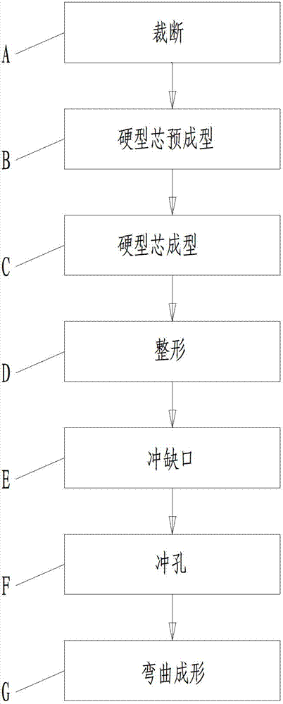
[0079] A method for forming a trailing arm beam of an automobile rear axle support assembly, the method comprises the following steps (see figure 1 shown in the flowchart):

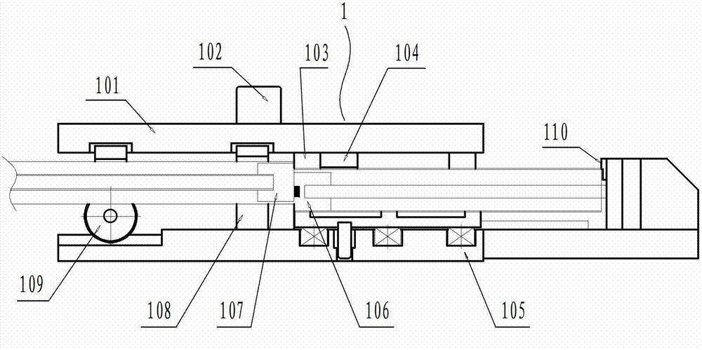
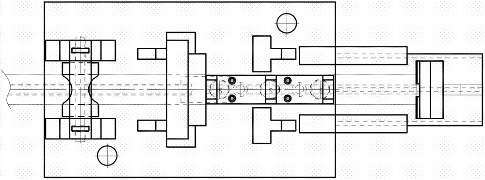
[0080] A. Cutting: Use cutting die 1 on the punching machine to cut the raw material tube into a fixed-length rough round tube 2;

[0081] B. Hard core preforming: using a hard core preforming die 3 on a hydraulic press to stamp the blank round tube 2 at one time into a preformed tube 4 with a straight round tube at one end and an arc-shaped round tube at the other end;

[0082] C. Hard core preforming: continue to use the hard core forming die 5 on the hydraulic press to punch the preformed tube 4 into a flat tube with an inclined straight tube at one end, a horizontal straight flat tube at one end, and a multi-section curved flat tube with variable cross-section in the middle. Rectangular hollow tube with variable cross-section 6 .

[0083] D. Reshaping: Reshape the variable-section rectangular hollow...


PUM


Abstract

The invention provides a molding method for a trailing arm beam of a rear axle bracket assembly of an automobile and relates to a production method for auto parts. The method includes the steps of A, cutting: cutting a raw tube into a rough round tube through a cutting die; B, hard core premolding: stamping the rough round tube into a preformed parison tube through a hard core premolding die; C, hard core premolding: stamping the preformed parison tube into a cross-section-variable rectangular hollow tube through the hard core premolding die; D, shaping; E, gap stamping: stamping a gap through a gap stamping die to obtain a cross-section-variable rectangular hollow tube with the gap; F, punching: punching through a punching die to obtain a semi-finished product of the trailing arm beam of the rear axle bracket assembly of the automobile; and G, bend molding: performing bend molding through a molding die to produce a finished product of the trailing arm beam of the rear axle bracket assembly of the automobile. According to the molding method, the production efficiency is high, the production cost is low, and the product quality is stable, so that mass production requirements can be satisfied.

Description

technical field [0001] The invention relates to a method for manufacturing auto parts, in particular to a method for forming a longitudinal arm beam of an automobile rear axle support assembly. Background technique [0002] The longitudinal arm beam of the automobile rear axle support assembly is a variable-section beam with an inclined straight flat tube at one end, a horizontal straight flat tube at the other end, and a multi-section curved flat tube with variable cross-section in the middle. The longitudinal arm beam is at the end of the inclined straight flat tube end. There is a gap, and a round hole is opened on the middle multi-section variable cross-section bent flat tube, which is difficult to manufacture. The existing manufacturing method of the trailing arm beam of the automobile rear axle support assembly generally includes the following processes: cutting, hard core preforming, hard core forming, shaping, cutting, drilling; wherein, the process cutting is genera...

Claims


Application Information

Patent Timeline
Patent Type & Authority Applications(China)
IPC IPC(8): B21D35/00B21D28/14B21D28/34B21D37/10B21D43/00
Inventor 洪山
Owner 柳州市昌河模具厂
Learn More