
Method for configuring alternative and dynamic drive of Z-direction main shafts of numerically-controlled machine tool with multiple Z-direction shafts and system thereof

A technology for CNC machine tools and spindles, which is applied in automatic control devices, feeding devices, metal processing machinery parts, etc.

Active Publication Date: 2013-02-13
CHANGZHOU MULTECH AUTOMATION TECH
View PDF5 Cites 10 Cited by
  • Summary
  • Abstract
  • Description
  • Claims
  • Application Information

AI Technical Summary

Problems solved by technology

[0002] At present, in the existing numerical control technology, the most commonly used is the XYZ three-axis linkage numerical control system. For some workpieces, such as craft wooden doors, it often needs to be clamped once, and the processing is completed by using multiple forming tools in rotation, and only one of them is used for each process. To process one tool, it is necessary to perform tool calibration for each tool separately, which is very troublesome and has a certain impact on the machining accuracy and efficiency of the CNC machine tool. Therefore, it is necessary to design a Z-direction spindle wheel drive configuration for a multi-Z-axis CNC machine tool. Method and system thereof, in order to improve the precision and efficiency of its processing

Method used


Image

  • Method for configuring alternative and dynamic drive of Z-direction main shafts of numerically-controlled machine tool with multiple Z-direction shafts and system thereof
  • Method for configuring alternative and dynamic drive of Z-direction main shafts of numerically-controlled machine tool with multiple Z-direction shafts and system thereof

Examples


Embodiment Construction

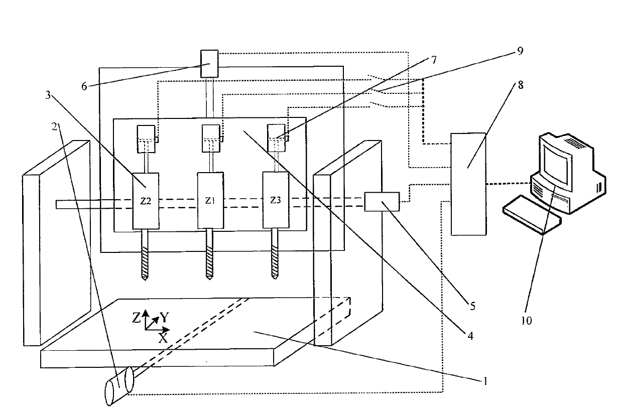
[0016] In order to make the content of the present invention easier to understand clearly, the present invention will be described in further detail below according to specific embodiments in conjunction with the accompanying drawings,

[0017] like figure 1 As shown, a Z-direction spindle wheel drive configuration method of a multi-Z-axis CNC machine tool, the steps of the method are as follows:

[0018] 1) Taking one of the Z-direction spindles 3 as the reference axis, measure the offset distance hX2, hX3...hXn of the tool tip relative to the reference axis in the X direction on the other Z-direction spindle 3 and the offset distance relative to the reference axis in the Y direction hY2, hY3...hYn;

[0019] 2) Carry out the mechanical zero return operation, and the mechanical coordinates are automatically set to zero;

[0020] 3) Set the tool fixing safety point, and drive the tool change cylinder 7 of each spindle through the multi-axis CNC control card 8 to control the Z...


PUM


Abstract

The invention discloses a method for configuring alternative and dynamic drive of Z-direction main shafts of a numerically-controlled machine tool with multiple Z-direction shafts and a system for configuring the alternative and dynamic drive of the Z-direction main shafts of the numerically-controlled machine tool with the multiple Z-direction shafts. The method mainly comprises the following steps that: a main shaft knife-changing cylinder is driven by a multi-shaft numerically-controlled control card to allow a reference axis to descend at low speed; the tool-setting on the reference axis is performed by a fixed tool-setting apparatus; a Z-direction tool-setting machine coordinate value jZ1 on the reference axis when a tool-setting in-place signal is triggered by a knife point of a knife on the reference axis, and an X-direction machine coordinate value jX1 and a Y-direction machine coordinate value jY1 which correspond to the reference axis at the moment are recorded; the jX1, the jY1 and the jZ1 are used as the workpiece origin values of the reference axis; and the main shaft knife-changing cylinder is driven by the multi-shaft numerically-controlled control card to enable the reference axis to return to a fixed safety point of the knife. The Z-direction main shafts can machine one workpiece alternatively to finish different working procedures on the same workpiece, so that save knife-changing time can be saved, and further, the machining precision and efficiency can be improved.

Description

technical field [0001] The invention relates to a Z-direction spindle wheel driving configuration method and system of a multi-Z-axis numerical control machine tool, and belongs to the technical field of multi-axis processing of numerical control machine tools. Background technique [0002] At present, in the existing numerical control technology, the most commonly used is the XYZ three-axis linkage numerical control system. For some workpieces, such as craft wooden doors, it often needs to be clamped once, and the processing is completed by using multiple forming tools in rotation, and only one of them is used for each process. To process one tool, it is necessary to perform tool calibration for each tool separately, which is very troublesome and has a certain impact on the machining accuracy and efficiency of the CNC machine tool. Therefore, it is necessary to design a Z-direction spindle wheel drive configuration for a multi-Z-axis CNC machine tool. The method and system ...

Claims


Application Information

Patent Timeline
IPC IPC(8): B23Q15/22
Inventor 史中权丁坤张明银李小军
Owner CHANGZHOU MULTECH AUTOMATION TECH
Learn More