Structure of truss manipulator

A technology of manipulators and trusses, applied in the field of automated machinery and equipment, can solve the problem of fewer special manipulators, achieve the effects of improving running stability, strengthening rigidity, and reducing running errors

Inactive Publication Date: 2013-02-13
苏州久工自动化科技有限公司
View PDF8 Cites 33 Cited by
  • Summary
  • Abstract
  • Description
  • Claims
  • Application Information

AI Technical Summary

Problems solved by technology

It is suitable for machine tool processing stations with high positioning accuracy requirements, but there are few special manipulators for loading and unloading links with relatively simple handling operations

Method used


Image

  • Structure of truss manipulator
  • Structure of truss manipulator
  • Structure of truss manipulator

Examples


Embodiment Construction

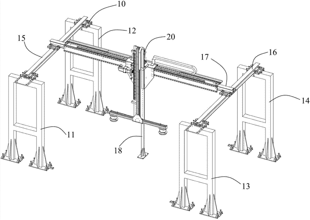
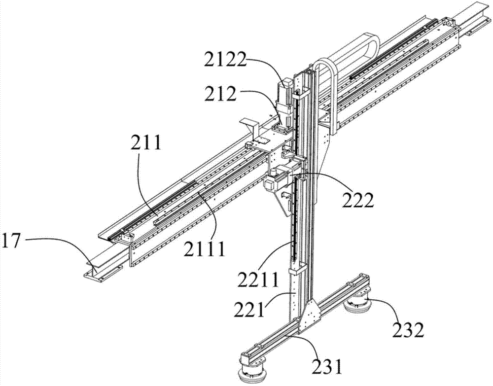
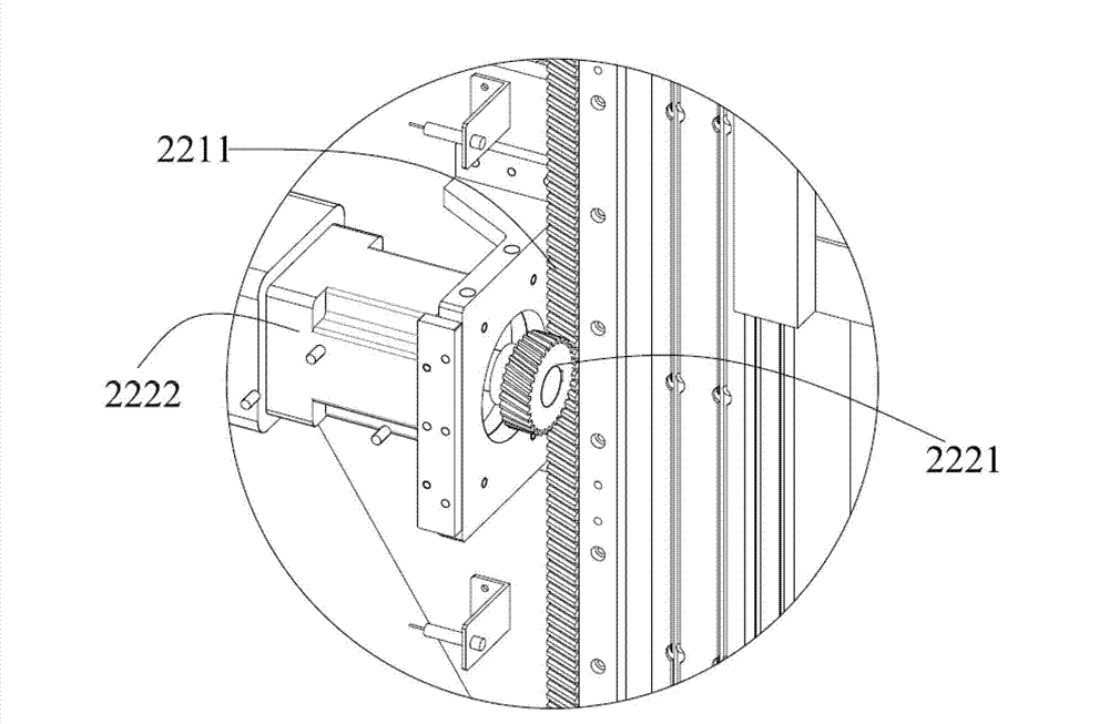
[0035] The invention discloses a truss manipulator structure, which comprises a truss and a manipulator arranged on the truss. The truss includes a plurality of support parts of a gantry structure, and beams for installing the manipulator are arranged on the support parts. The manipulator is a two-degree-of-freedom manipulator. The manipulator includes installation The horizontal movement component on the beam and the vertical movement component vertically installed on the horizontal movement component. The bottom of the vertical movement component is connected with a three-claw gripper. The horizontal movement component and the vertical movement component respectively include a gear and a rack for transmission. The gear and the rack are set as helical teeth meshing with each other.

[0036] Further, the truss includes two sets of supporting groups arranged in parallel, and each supporting group includes two supporting parts and a connecting part connecting the intermediate pos...


PUM


Abstract

The invention discloses a structure of a truss manipulator. The structure of the truss manipulator comprises a truss and a manipulator arranged on the truss, wherein the truss comprises a plurality of support sections with portal structures; a beam for installing the manipulator is arranged on each support section; the manipulator is a two-freedom manipulator; the manipulator comprises a horizontal movement subassembly arranged on the beam and a vertical movement subassembly vertically arranged on the horizontal movement subassembly; a three-claw clamper is arranged at the bottom of the vertical movement subassembly; and the horizontal movement subassembly and the vertical movement subassembly respectively comprise gears and racks for driving, and the gears and the racks are meshed skewed teeth. The truss manipulator disclosed by the invention is simple and reliable in structure and low in cost, and the gears and the racks drive by meshing of the skewed teeth. Thus, the mechanical work load is increased and the operation stability is also improved.

Description

technical field [0001] The invention relates to the technical field of automatic mechanical equipment, in particular to a truss manipulator structure. Background technique [0002] In the industrial automation production line, workpieces often need to be moved back and forth between the assembly line and the machine tool processing station. At present, the loading and unloading of machine tools is realized on the automatic assembly line, and general industrial robots or special manipulators are widely used. [0003] General-purpose industrial robots have large loads, high precision, and programmable actions, but they are expensive and uneconomical to use when the handling path is relatively simple. At present, special manipulators are generally used in occasions with low precision requirements, such as material warehouses, processing with low positioning requirements, or loading and unloading links of process equipment. There are few special manipulators suitable for machi...

Claims


Application Information

Patent Timeline
Patent Type & Authority Applications(China)
IPC IPC(8): B25J9/10B23Q7/04
Inventor 雷恩·李·哈里森张淑云
Owner 苏州久工自动化科技有限公司
Why Eureka
Try Eureka