Inflation/deflation type air bag unfolding and coiling device

An inflatable, inflatable and unfolding technology, which is used in ground installations, transportation and packaging, and aircraft component testing, etc. Difficulties and other problems, to achieve the effect of solving the difficulty of folding and unfolding control, simple structure and reasonable design

Inactive Publication Date: 2013-02-13
HARBIN INST OF TECH
View PDF4 Cites 2 Cited by
  • Summary
  • Abstract
  • Description
  • Claims
  • Application Information

AI Technical Summary

Problems solved by technology

[0003] The purpose of the present invention is to solve the problem that the inflatable structure of the existing aerospace vehicle is flexible and difficult to control the folding and unfolding. It is necessary to simulate the folding and unfolding process in the working state in the ground simulation experiment, but there is no unfolding that can realize the auxiliary folding and unfolding function and can be controlled. To solve the problem of the rolling device, and then provide an inflatable and deflated airbag unrolling device

Method used


Image

  • Inflation/deflation type air bag unfolding and coiling device
  • Inflation/deflation type air bag unfolding and coiling device
  • Inflation/deflation type air bag unfolding and coiling device

Examples


specific Embodiment approach 1

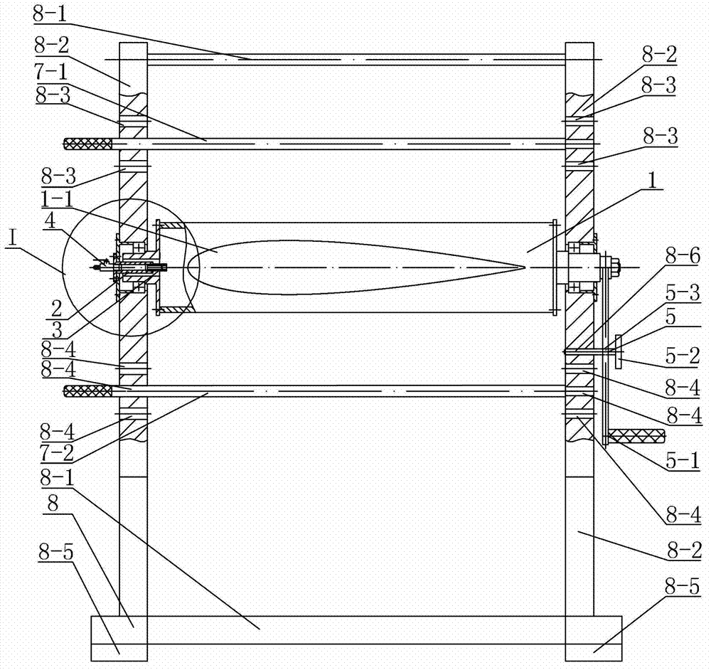
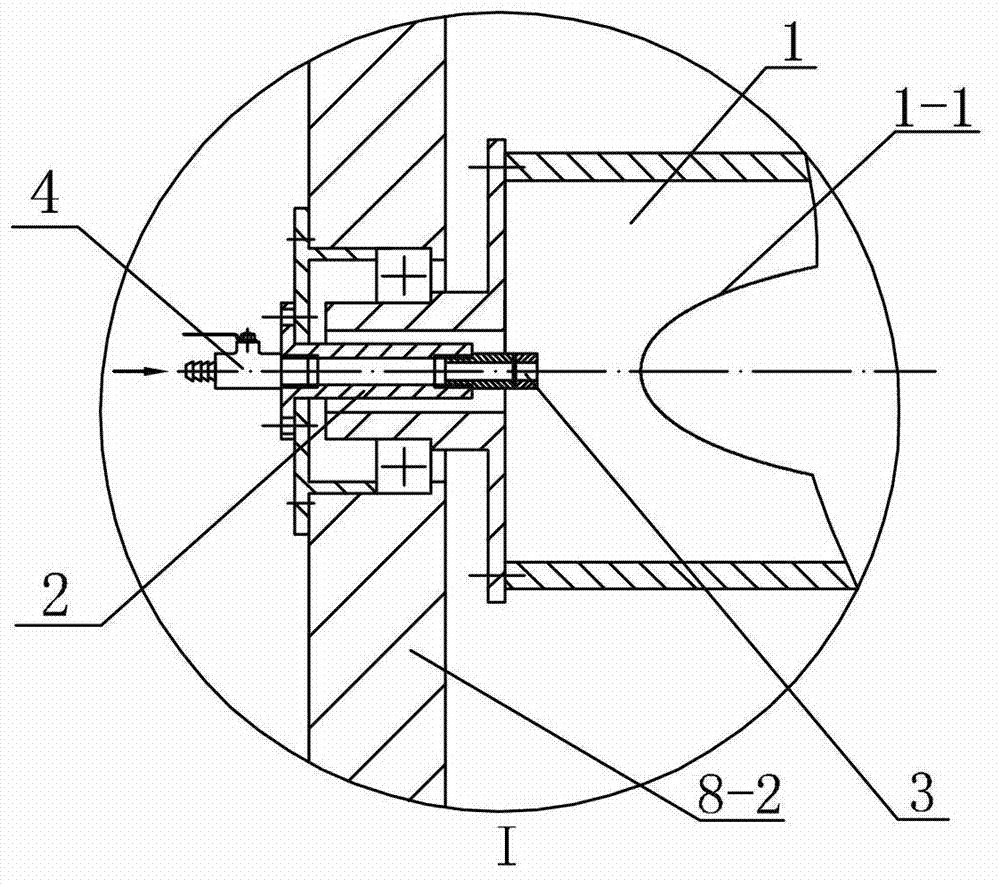
[0007] Specific implementation mode one: combine Figure 1-Figure 7 Describe this embodiment. An inflatable and deflated airbag unwinding device in this embodiment includes a center shaft 1, a drive lock mechanism 5, a support 8, an upper limit gear lever 7-1, a lower limit gear lever 7-2 and a ventilator. Mechanism, the ventilation mechanism includes a ventilation pipe 2, a rotary joint 3 and an air valve 4, and the support 8 includes a base 8-5, two beams 8-1 and two vertical beams 8-2, and two vertical beams 8- 2 is fixed on the base 8-5, two vertical beams 8-2 are arranged side by side, and the upper and lower ends of the two vertical beams 8-2 are respectively provided with cross beams 8-1 connected with the two, and the central axis 1 It is a hollow shaft, and the opposite side walls of the central shaft 1 are respectively provided with holes 1-1 in the same cross-sectional shape as the airbag 9 along its length direction, and the two holes 1-1 are oppositely arranged, a...

specific Embodiment approach 2

[0008] Specific implementation mode two: combination figure 1 Describe this embodiment, the drive locking mechanism 5 described in this embodiment includes a rocker arm 5-1 and a pin 5-2, the other end of the central axis 1 is connected to the rocker arm 5-1, and the lower side of the central axis 1 and the center The vertical beam 8-2 connected to the other end of the shaft 1 is provided with a first through hole 8-6, and the rocker arm 5-1 is provided with a second through hole 5-3, and shaking the rocker arm 5-1 can drive the axis 1 to rotate , when the second through hole 5-3 on the rocker arm 5-1 coincides with the first through hole 8-6 on the vertical beam 8-2, the first through hole 8-6 and the second through hole 5- 3. The pin 5-2 is pierced, which is used to control the rotation of the central shaft 1 and keep the inflated and deployed airbag 9 pierced on the central shaft 1 parallel to the ground. Such setting can realize the manual power input of the rotation of t...

specific Embodiment approach 3

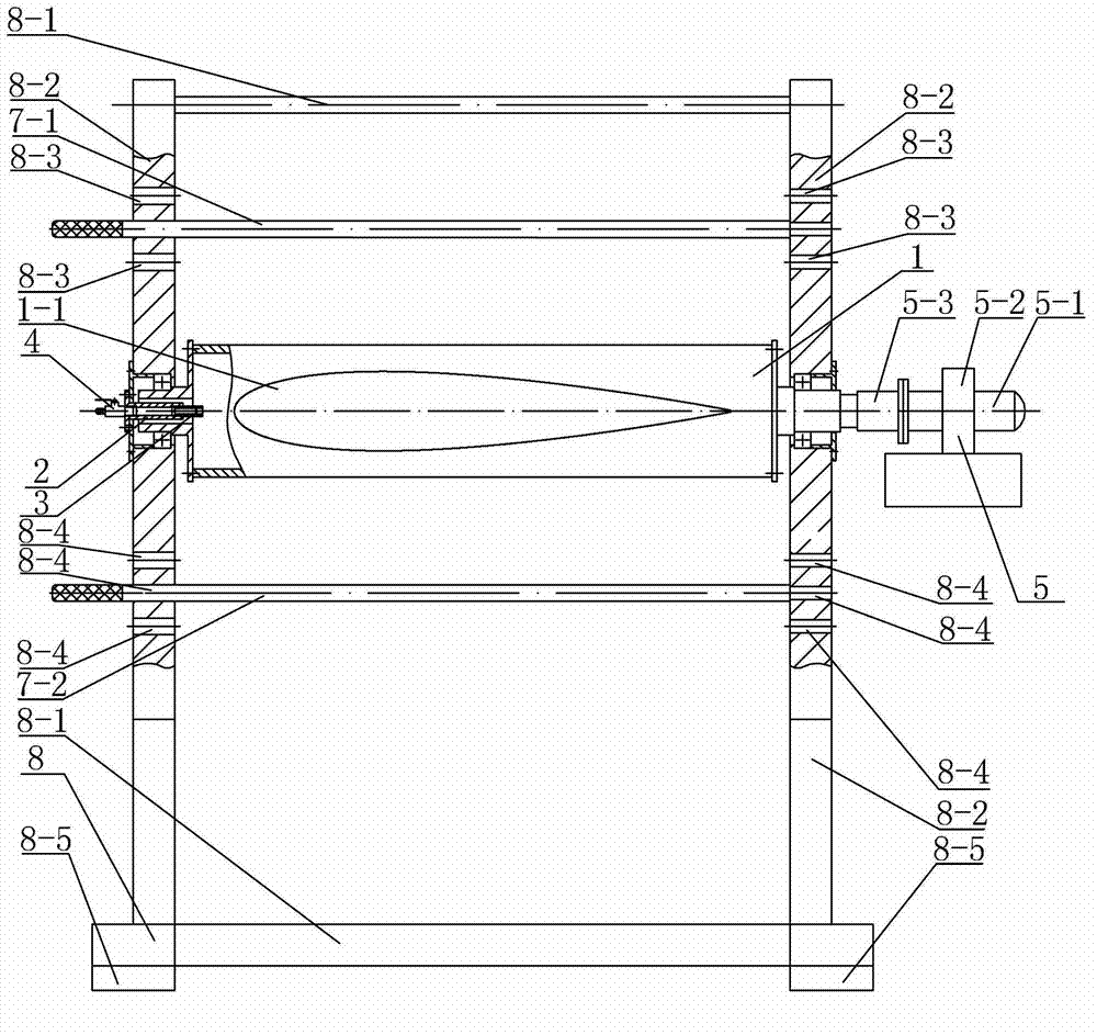
[0009] Specific implementation mode three: combination image 3 Describe this embodiment, the drive locking mechanism 5 described in this embodiment includes motor 5-1, speed reducer 5-2 and coupling 5-3, motor 5-1 and speed reducer 5-2 are connected, speed reducer 5-2 The other end of the central axis 1 is connected through the coupling 5-3, and the start and stop of the motor 5-1 is used to control the start and stop of the central axis 1, thereby keeping the inflated and deployed airbag 9 pierced on the central axis 1 in contact with the ground. parallel. Such setting can realize the automatic control of the rotation of the central axis, and can ensure that the air bag filled with gas passing through the central axis is parallel to the ground, which meets the design and actual needs. Others are the same as in the first embodiment.


PUM


Abstract

An inflation/deflation type air bag unfolding and coiling device relates to an unfolding and coiling device, and aims to solve the problem that in a conventional aviation spacecraft, the inflation structure is highly flexible, the folding and coiling are controlled difficultly, and the folding and unfolding process in the working state needs to be simulated and experimented on the ground, but no unfolding and coiling device capable of achieving the function of assisting the folding and the unfolding and unfolding controllability is available. The inflation/deflation type air bag unfolding and coiling device comprises a middle shaft, a driving and locking mechanism, a support saddle, an upper limiting stop lever, a lower limiting stop lever and a ventilation mechanism, wherein the ventilation mechanism comprises a ventilation connecting pipe, a rotary joint and an air valve; the support saddle comprises a base, two cross beams and two vertical beams; the middle shaft is arranged on the two vertical beams positioned between the two cross beams and can be rotated in the circumferential direction; the ventilation connecting pipe is connected to one vertical beam; the air valve is connected to the end part, opposite to the rotary joint, of the ventilation connecting pipe; and the other end of the middle shaft is connected with the driving and locking mechanism used for controlling the rotation and the stopping of the middle shaft. The device is used for inflatable structures of large-scale aviation spacecrafts.

Description

technical field [0001] The invention relates to an unwinding device, in particular to an inflatable and deflated airbag unwinding and rolling device. Background technique [0002] The large-scale aerospace inflatable structure needs to be folded and packaged on the ground for storage, and then inflated and unfolded after entering the work area to work normally. Due to the high flexibility of the inflatable structure and the difficulty in controlling the folding and unfolding, it is necessary to simulate the folding and unfolding process in the working state of the experiment on the ground. It is urgent to provide an unwinding device that can realize the auxiliary folding and unfolding function and controllable unfolding. Contents of the invention [0003] The purpose of the present invention is to solve the problem that the inflatable structure of the existing aerospace vehicle is flexible and difficult to control the folding and unfolding. It is necessary to simulate the ...

Claims


Application Information

Patent Timeline
Patent Type & Authority Applications(China)
IPC IPC(8): B64F5/00B64F5/60
Inventor 王长国周涛刘远鹏夏震猛龚芃谭惠丰
Owner HARBIN INST OF TECH
Why Eureka
Try Eureka