Air injection vortex spinning device with pumping component

A vortex spinning and suction element technology, applied in the field of air-jet vortex spinning devices, can solve the problems of fiber loss or fiber loss, generation of yarn details, deterioration of yarn evenness, etc., so as to improve the utilization rate and reduce false twist. , reducing the effect of high fiber loss

Inactive Publication Date: 2013-02-13
DONGHUA UNIV
View PDF10 Cites 5 Cited by
  • Summary
  • Abstract
  • Description
  • Claims
  • Application Information

AI Technical Summary

Problems solved by technology

This causes this known spinning method to produce a large amount of tow or fiber loss during the formation of the yarn
Increased fiber tow will result in light weight of fiber sliver, yarn fineness, deterioration of yarn dryness, and higher processing costs

Method used


Image

  • Air injection vortex spinning device with pumping component
  • Air injection vortex spinning device with pumping component
  • Air injection vortex spinning device with pumping component

Examples


Embodiment 1

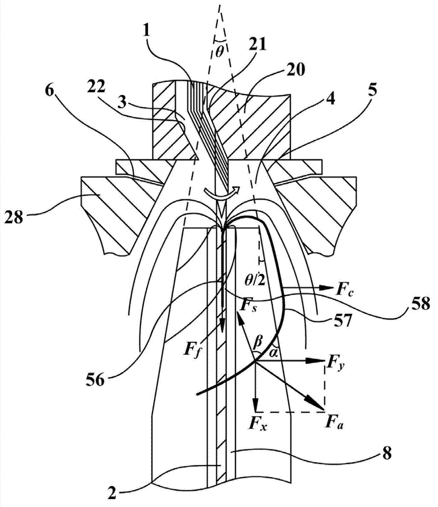
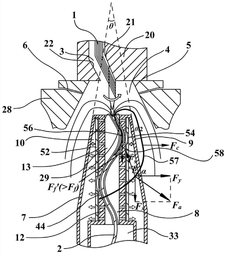
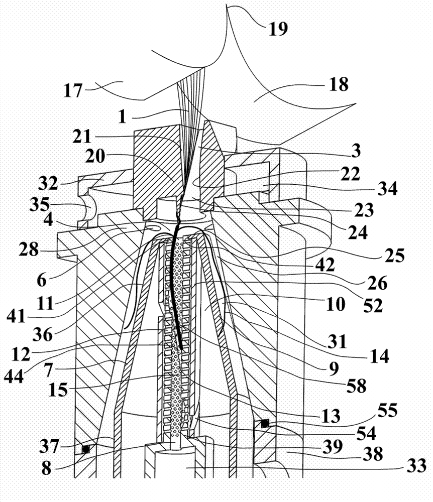
[0032] A threaded yarn introducing channel 8 with a circular cross-section is provided inside the yarn introducing cone 7 along its central axis, for outputting the spun yarn 2 from the twisting zone. The yarn delivery channel 8 is divided into a small diameter section 29 near the inlet 11 and a large diameter section 33 near the outlet 40 . The interior of the wall shell 9 of the yarn drawing cone 7 shown in this embodiment is set to be hollow, so as to form a continuous cavity 10 around the yarn drawing channel 8 and in the circumferential direction of the yarn drawing cone 7 . Simultaneously, in the small-diameter section 29 of the yarn-drawing passage 8, a central line is provided on the side wall 12 between the above-mentioned cavity 10 and the yarn-drawing passage 8 along the radial direction of the circular cross-section of the yarn-drawing passage 8, and the section is a circle. Shaped through hole 13. The through-holes 13 are arranged in several layers in the axial d...

Embodiment 2

[0049] The difference between embodiment 2 and embodiment 1 is mainly the cross-sectional shape of the spiral groove 44, such as Figure 10 shown. In this embodiment, the cross-sectional shape of the spiral groove 44 of the small-diameter section 29 of the yarn guiding channel is circular.


PUM

PropertyMeasurementUnit
diameteraaaaaaaaaa
angleaaaaaaaaaa

Abstract

The invention relates to an air injection vortex spinning device with a pumping component. A section, which closes to an inlet of a yarn-guiding channel, of the yarn-guiding channel is a minor diameter section, and the diameter of the minor diameter section is small. A section, which closes to an outlet of the yarn-guiding channel, of the yarn-guiding channel is a major diameter section, and the diameter of the major diameter section is big. A yarn-guiding cone is hollow, and the shape of a cavity of the hollow portion inside the yarn-guiding cone is generally the same with the shape of an outer outline. Small holes communicated with the yarn-guiding channel and the cavity are arranged on the side wall of the minor diameter section, and the small holes are evenly distributed on the side wall of the minor diameter section. A screwy groove is formed in the inner wall of the minor diameter section of the yarn-guiding channel, and a screwy shape of the groove shares the same axis with an axial direction of the yarn-guiding channel. A plug-in module is placed inside the cavity of the minor diameter section of the yarn-guiding channel, the plug-in module is generally of a round tube shape, and the inner diameter of the plug-in module is larger than the external diameter of the minor diameter section. A screwy gap communicated with the tube wall is arranged on the side wall of the plug-in module, and the screwy gap is matched with the groove. According to the air injection vortex spinning device with the pumping component, fiber loss is reduced by utilizing pumping and inhalation of flow, yarn evenness is improved, yarn twist is increased, and finer yarns with a compact structure can be produced.

Description

technical field [0001] The invention belongs to the technical field of spinning equipment, in particular to an air-jet vortex spinning device with a suction element. Background technique [0002] The spinning devices used in the known spinning technology for producing spun yarns by means of high-speed rotating air vortex, such as the published Chinese patents CN 101748520A (belonging to Murata Corporation of Japan) and CN 102165111A (belonging to Rieter Corporation of Switzerland). The inlet section of the device includes a fiber feed channel. In the exit area of ​​the fiber feed channel there is a twist blocking element (e.g. a concentric needle around which the fibers are guided, or a protrusion on the fiber guiding surface which deflects the passing fiber bundles ). [0003] An annular vortex chamber is provided downstream of the outlet area of ​​the fiber feeding channel, and a number of injection holes tangent to it are provided on the peripheral wall of the vortex ch...

Claims


Application Information

Patent Timeline
Patent Type & Authority Applications(China)
IPC IPC(8): D01H4/02D01H4/38
CPCD01H1/115
Inventor 裴泽光马乾坤
Owner DONGHUA UNIV
Why Eureka
Try Eureka