
Rotational speed control method for pilot injection type numerical control air-powered engine

A pneumatic engine, speed control technology, applied in the direction of engine components, machines/engines, mechanical equipment, etc., can solve the problems of inconvenient operation of the speed control device, and achieve the effect of enhancing practicability

Inactive Publication Date: 2013-02-13
JIANGSU UNIV
View PDF7 Cites 4 Cited by
  • Summary
  • Abstract
  • Description
  • Claims
  • Application Information

AI Technical Summary

Problems solved by technology

[0006] In order to overcome the defect of inconvenient operation of the existing pre-injection numerical control pneumatic engine speed control device, the present invention provides a speed control method for the pre-injection numerical control air engine which is simple in structure, easy to operate, low in cost and easy to adapt to real-time load. method to accurately and quickly respond to the rotational speed manipulation of a pre-injection numerically controlled air motor

Method used


Image

  • Rotational speed control method for pilot injection type numerical control air-powered engine
  • Rotational speed control method for pilot injection type numerical control air-powered engine

Examples


Embodiment Construction

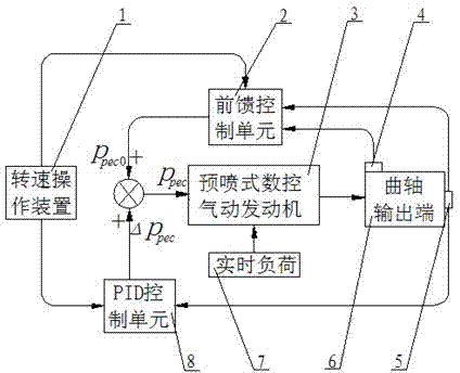
[0021] Such as figure 1 As shown, the torque sensor 4 and the rotational speed sensor 5 are fixedly installed on the crankshaft output end 6 of the pre-injection numerically controlled air motor 3, the rotational speed sensor 5 is connected to the feedforward control unit 2 and the PID control unit 8, and the torque sensor 4 is connected to the feedforward control unit 2.

[0022] The pre-injection numerical control pneumatic engine 3 is affected by the real-time load 7, which causes the change of the output end 6 of the crankshaft, and the torque sensor 4 will measure the torque value of the output end 6 of the crankshaft M p Input to the feed-forward control unit 2 through the signal line, and the speed sensor 5 will output the real-time speed of the crankshaft output 6 n r (unit: rev / min) are respectively input to the feed-forward control unit 2 and the PID control unit 8. In order to eliminate the fluctuation of the rotational speed, the real-time rotational speed inpu...


PUM


Abstract

The invention discloses a rotational speed control method for a pilot injection type numerical control air-powered engine. The method comprises the following steps of: respectively inputting an expected rotational speed into a feed forward control unit and a proportion integration differentiation (PID) control unit through a rotational speed operating device, respectively inputting real-time rotational speed to the feed forward control unit and the PID control unit through a rotational speed sensor, and inputting a torque measuring value at an output end of a crankshaft to the feed forward control unit through a torque sensor; calculating a mean load at the expected rotational speed through feed forward control; calculating master control pressure which corresponds to the expected rotational speed, calculating difference between the expected rotational speed and a real-time rotational speed filtering value through the PID control unit, and calculating the fine-tuning control pressure; and finally, taking the sum of the master control pressure and the fine-tuning control pressure as integral control pressure, inputting the integral control pressure to a pilot injection cylinder of the pilot injection type numerical control air-powered engine, and performing rotational speed operation on the pilot injection type numerical control air-powered engine. By the method, the change of real-time load and the rotational speed operation of the pilot injection type numerical control air-powered engine can be conveniently, accurately and rapidly reflected.

Description

technical field [0001] The invention belongs to the technical field of rotational speed control of pneumatic motors, in particular to a rotational speed control method of a pre-spray numerical control pneumatic motor. Background technique [0002] Pneumatic motors use compressed air from a wide range of sources as "fuel" and emit no pollution. They are truly "zero-emission" and environmentally friendly power sources. It can provide driving power for environmentally friendly and energy-saving vehicles. Its function is to convert the pressure energy of compressed air into the mechanical energy of crankshaft rotation to drive the vehicle. [0003] Pneumatic motors are generally composed of air storage tanks, engine bodies, pressure reducing valves, flow control valves, and gas pipelines. The compressed air stored in the air storage tank passes through the air pipeline, pressure reducing valve, flow regulating valve, air inlet, cylinder and exhaust port, and finally enters the ...

Claims


Application Information

Patent Timeline
Patent Type & Authority Applications(China)
IPC IPC(8): F01B25/00
Inventor 陈士安张世金何仁王胜张晓娜赵廉健汤哲鹤
Owner JIANGSU UNIV
Learn More