Micropump being easy to assemble
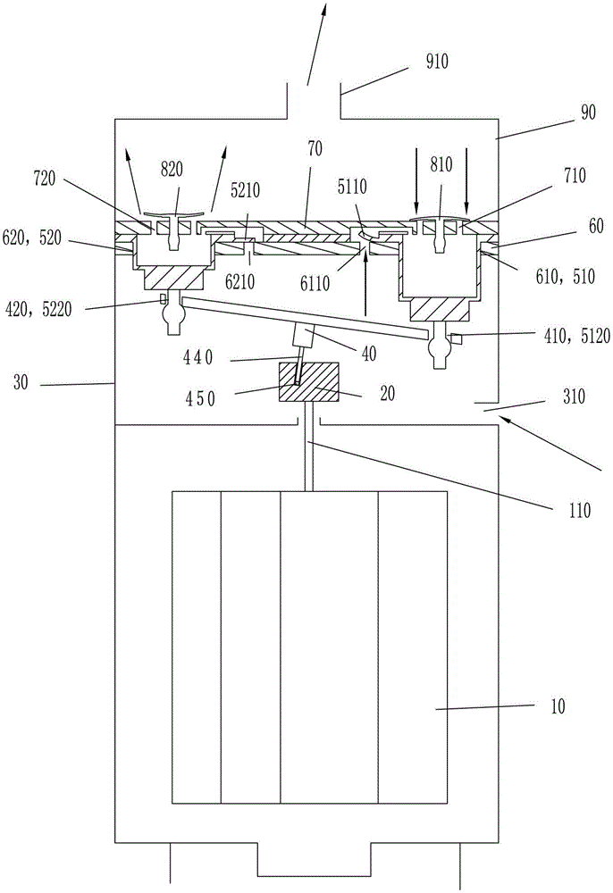
A micro-pump and exhaust valve technology, which is used in pump components, variable-capacity pump components, and liquid variable-capacity machinery, etc., can solve the problem of missing exhaust valve plates, delayed construction periods, and inadequate installation of exhaust valve plates. and other problems, to achieve the effect of improving the speed of assembly, reducing working noise, and good promotion potential.
- Summary
- Abstract
- Description
- Claims
- Application Information
AI Technical Summary
Problems solved by technology
Method used
Image
Examples
Embodiment 1
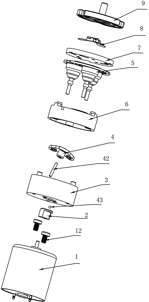
[0048] For the unfolded structure of an embodiment of the micropump that is easy to assemble of the present invention, please refer to figure 2 . The easy-to-assemble micropump has a motor 1, an eccentric wheel 2, a base 3, a steel needle 42, a ball 43, an umbrella-shaped connecting rod 4, a piston body 5, a cylinder plate 6, an air chamber pressure plate 7, an exhaust valve plate group 8 and upper cover9.
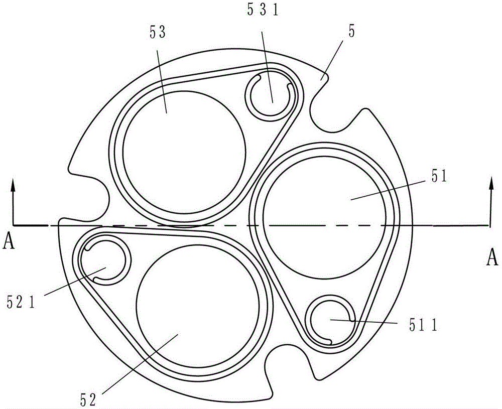
[0049] Please see image 3 and Figure 4 : Piston body 5 made of rubber, three hollow pistons 51, 52, 53 extending downward and three intake valve plates 511, 521, 531 evenly distributed on the flat plate portion of its upper end, three pistons 51, 52 The lower ends of , 53 are respectively provided with engaging portions 512 , 522 , 532 extending downward.
[0050] Please see Figure 5 and Figure 6 The three pistons 51, 52, 53 corresponding to the piston body 5 on the cylinder plate 6 are provided with three corresponding cylinder holes 61, 62, 63. The upper surf...
Embodiment 2
[0060] Another embodiment of the micropump that is easy to assemble of the present invention has motor 1, eccentric wheel 2, base 3, steel needle 44, ball 45, umbrella-shaped connecting rod 4, piston body 5 and cylinder plate 6 as previous embodiment, for Their structures and connections will not be described in detail. But the structure and connection relationship of the air chamber pressing plate 7', the exhaust valve sheet group 8' and the loam cake 9' in the present embodiment are different from the previous embodiment.
[0061] Please see Figure 16 Three pistons 51, 52, 53 corresponding to the piston body 5 on the air chamber pressing plate 7 ' are provided with three corresponding exhaust holes 71 ', 72 ', 73 '. In the middle of the upper end surface of the air chamber pressure plate 7', corresponding to the three exhaust holes 71', 72', 73', a triangular central groove 701' is arranged. The air holes 71', 72', 73' are respectively provided with circular grooves 705',...
Embodiment 3
[0069]Another embodiment of the micropump that is easy to assemble of the present invention has motor 1, eccentric wheel 2, base 3, steel needle 44, ball 45, umbrella-shaped connecting rod 4, piston body 5 and cylinder plate 6 as first embodiment, Their structures and connection relationships will not be described in detail. However, the structure and connection relationship of the air chamber pressing plate 7 ″, the exhaust valve sheet group 8 ″ and the upper cover 9 ″ in this embodiment are different from those in the first embodiment.
[0070] Please see Figure 20 : Three pistons 51, 52, 53 corresponding to the piston body 5 on the air chamber pressure plate 7" are provided with three corresponding exhaust holes 71", 72", 73". Corresponding to the three exhaust holes 71", 72", and 73" in the middle of the upper end surface of the air chamber pressure plate 7, a triangular central groove 701" with a side line concave inward is provided, and on the three vertices of the cen...
PUM
 Abstract
Description
Claims
Application Information
 - R&D
- Intellectual Property
- Life Sciences
- Materials
- Tech Scout
- Unparalleled Data Quality
- Higher Quality Content
- 60% Fewer Hallucinations
Browse by: Latest US Patents, China's latest patents, Technical Efficacy Thesaurus, Application Domain, Technology Topic, Popular Technical Reports.
© 2025 PatSnap. All rights reserved.Legal|Privacy policy|Modern Slavery Act Transparency Statement|Sitemap|About US| Contact US: help@patsnap.com


