Light guide plate and manufacturing method of light guide plate as well as backlight module and display device

A manufacturing method and a technology of a light guide plate, which are applied to manufacturing tools, lighting devices, fixed lighting devices, etc., can solve the problem of uneven light and shade on the exit surface of the light guide plate, insufficient adjustment of the luminance of the light guide plate, and unclear images on the liquid crystal display and other issues, to achieve the effect of realizing automatic mass production of mold core engraving, increasing and affecting the definition, increasing the brightness of the image and affecting the definition

Inactive Publication Date: 2013-02-13
BOE TECH GRP CO LTD +1
View PDF4 Cites 14 Cited by
  • Summary
  • Abstract
  • Description
  • Claims
  • Application Information

AI Technical Summary

Problems solved by technology

[0003] A light source is provided on at least one side of the light guide plate in the side-type backlight module, which will cause uneven light on the exit surface of the light guide plate; it is bright near the light source and dark away from the light source; in order to solve this problem, the prior art is Set dots on the bottom surface of the light guide plate, and use the principle of diffuse reflection to scatter the fully reflected light in the light guide plate through the dots to adjust the uniformity of the light; although this kind of light guide plate with dots can solve the problem of light emission from the light guide plate to a certain extent The problem of uneven light and shade on the surface, but the adjustment of the luminance of this kind of light guide plate is not thorough enough, and because the direction of scattered light is too scattered, the light cannot be converged, resulting in low display brightness of the light guide plate, which in turn leads to poor images on the LCD screen. Clear; at present, there are many methods for manufacturing light guide plates with dots. Usually, diamond cutters are used to process mesh surface mold cores on copper mold core substrates, and then injection molding is used to obtain light guide plates. However, the hardness of copper mold core substrates used in this process method is Poor casting life, low casting life, unable to meet mass production requirements; if the mold core substrate is engraved with a diamond knife, it will lead to problems such as low engraving accuracy of the mold core and rough surface of the mold core, so that the mold core produced by using the mold core The dot surface of the light guide plate is rough, which cannot meet the quality requirements; because the light guide plate has higher requirements on precision, this process method cannot currently manufacture it; in view of the above deficiencies, the present invention urgently needs to provide a new light guide plate and the light guide plate. Manufacturing method of light board

Method used


Image

  • Light guide plate and manufacturing method of light guide plate as well as backlight module and display device
  • Light guide plate and manufacturing method of light guide plate as well as backlight module and display device
  • Light guide plate and manufacturing method of light guide plate as well as backlight module and display device

Examples


Embodiment Construction

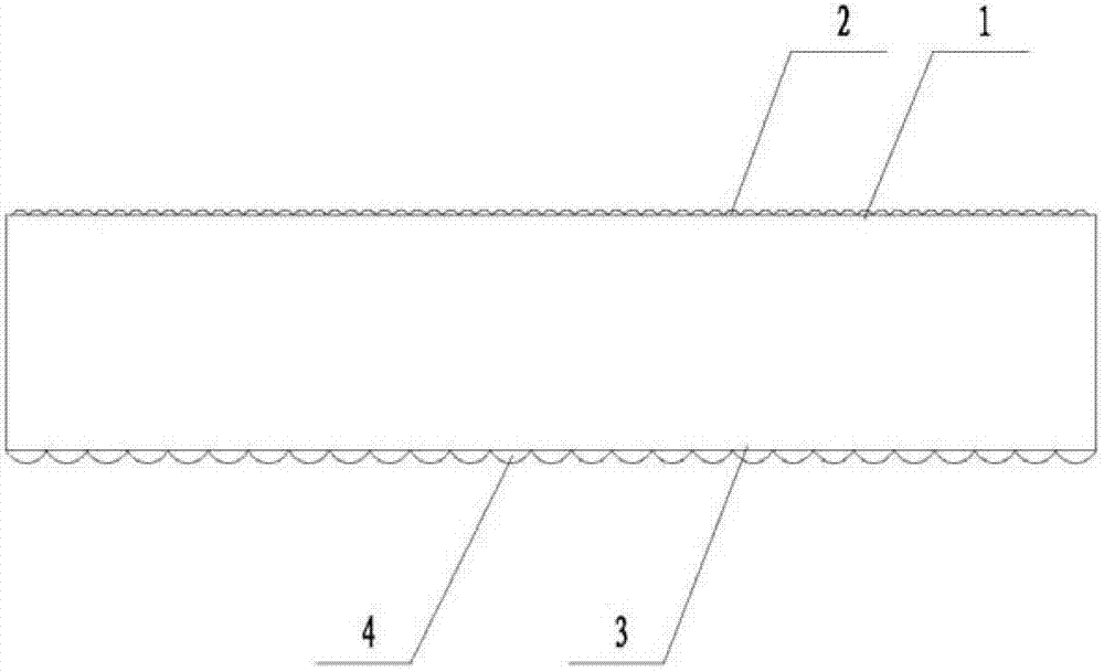
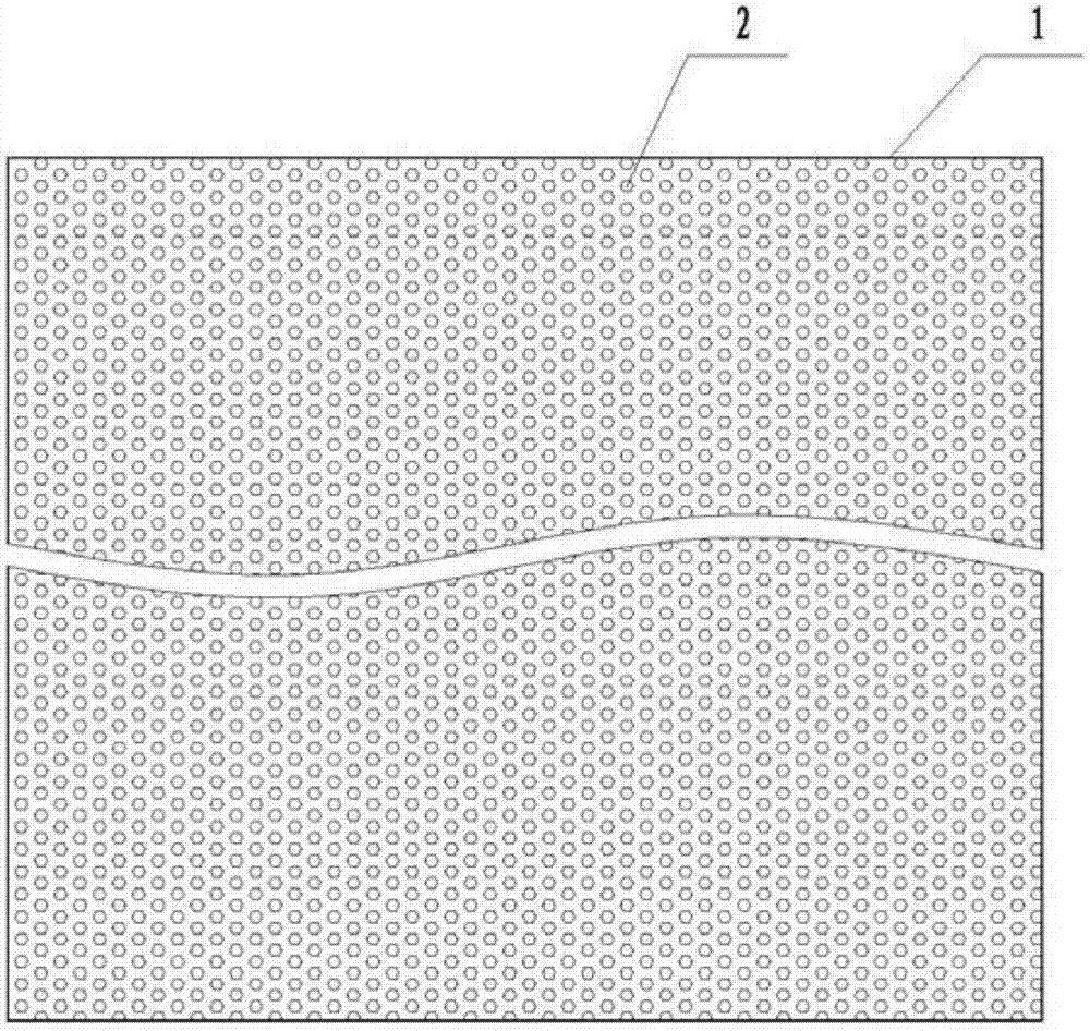
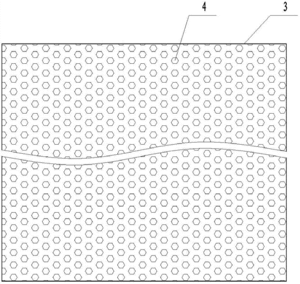
[0037] see figure 1 , figure 2 , image 3 As shown, a light guide plate in this embodiment includes a light guide plate base material, and the light guide plate base material includes an incident surface for receiving light beams, a bottom surface connected to the incident surface, a bottom surface connected to the incident surface and connected to the incident surface. The exit surface opposite to the bottom surface, one side opposite to the incident surface and the remaining opposite sides, the exit surface at the top of the light guide plate is provided with a micro-transmission surface 1; the micro-transmission surface includes a plurality of evenly distributed micro-transmission points 2; The micro-transparency point is provided with an outer convex surface, and the outer convex surface is an arc-shaped mirror surface that can collect light; Adjust to gather the scattered light; increase the display brightness and affect the clarity of the liquid crystal display, and i...


PUM

PropertyMeasurementUnit
thicknessaaaaaaaaaa
depthaaaaaaaaaa
depthaaaaaaaaaa

Abstract

The invention relates to the technical field of display and particularly relates to a light guide plate capable of utilizing a micro-penetration surface to collect light and a manufacturing method of the light guide plate as well as a backlight module and a display device. An emergent surface of the light guide plate is the micro-penetration surface; the micro-penetration surface comprises a plurality of micro-penetration points and the micro-penetration points are provided with convex surfaces; and the bottom surface of the light guide plate is a net surface and the net surface comprises a plurality of net points and the net points are provided with convex surfaces. The manufacturing method of the light guide plate comprises the steps of: presetting a micro-penetration point distribution pattern by a precision engraving machine; putting a micro-penetration surface die core base plate into a precision engraving machine; engraving the micro-penetration surface die core base plate into a micro-penetration face die core according to the micro-penetration point distribution pattern; assembling the micro-penetration surface die core and a light guide plate die core into a light guide plate die; and injecting and molding into the light guide plate by the light guide plate die. A micro-penetration surface design is adopted and directions of all scattering lights in the light guide plate can be adjusted by using the micro-penetration surface to collect the scattering lights; and the development brightness and the influence definition of a liquid crystal liquid screen are improved and the product quality is improved.

Description

technical field [0001] The invention relates to the field of display technology, in particular to a light guide plate capable of concentrating light by utilizing a micro-transparent surface, a manufacturing method thereof, a backlight module and a display device. Background technique [0002] Since the liquid crystal molecules themselves do not have the ability to emit light, an external light source is required in the existing liquid crystal display to obtain a display image. According to the relative position of the light source, the backlight can be divided into side-type and direct-type. In the side-lit backlight structure, the light source is placed on the side of the light guide plate, and the light source emitted by the light bar is directly injected into the light guide plate; the main function of the light guide plate is to convert the parallel light incident on the side into planar light. In the direct-lit backlight structure, the light source is placed under the ...

Claims


Application Information

Patent Timeline
Patent Type & Authority Applications(China)
IPC IPC(8): G02B6/00B29D7/00B24B29/02F21S8/00G02F1/13357F21Y101/02
Inventor 龙登武
Owner BOE TECH GRP CO LTD
Why Eureka
Try Eureka