Optical unit, method of producing the same, and image pickup apparatus

An optical unit, image pickup element technology, applied in optical elements, chemical instruments and methods, optics, etc., can solve the problems of characteristic failure, film unevenness, pinholes, etc., and achieve the effect of easy precision

Inactive Publication Date: 2013-02-13
SONY CORP
View PDF13 Cites 3 Cited by
  • Summary
  • Abstract
  • Description
  • Claims
  • Application Information

AI Technical Summary

Problems solved by technology

[0022] In particular, it is difficult to form a uniform film of an IR cut filter on an uneven surface, causing problems such as film unevenness, pinholes, and characteristic failure

Method used


Image

  • Optical unit, method of producing the same, and image pickup apparatus
  • Optical unit, method of producing the same, and image pickup apparatus
  • Optical unit, method of producing the same, and image pickup apparatus

Examples


Embodiment Construction

[0048] Embodiments of the present technology will be described below with reference to the drawings.

[0049] It will be explained in the following order:

[0050] 1. The first structural example of the optical unit;

[0051] 2. The second structural example of the optical unit;

[0052] 3. The third construction example of the optical unit;

[0053] 4. A method of manufacturing an optical unit; and

[0054] 5. A configuration example of an image pickup device.

[0055]

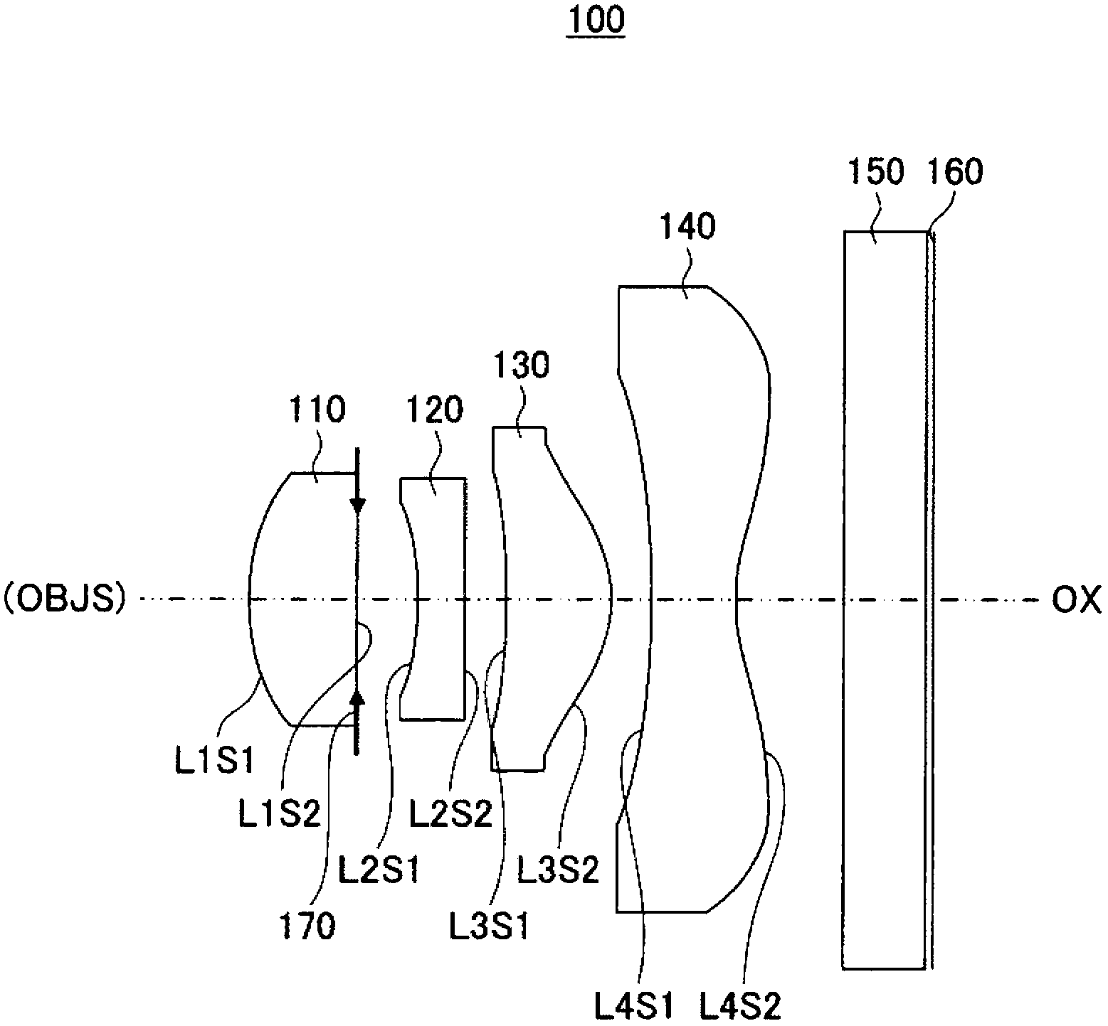
[0056] figure 1 is a diagram showing a first configuration example of the optical unit according to the present embodiment.

[0057] The optical unit 100 according to the present embodiment includes a plurality of (four in the present embodiment) lenses arranged along the optical path from the object side OBJS toward the image side.

[0058] In the optical unit 100 , the image-side surface or the object-side surface (the image-side surface in this embodiment) of one of the plurality of lenses is a waf...


PUM


Abstract

An optical unit includes a plurality of lenses arranged along an optical path from an object side toward an image side, the plurality of lenses including at least one lens including an image side surface and an object side surface, one of which is formed to be an aspheric surface at wafer level, the aspheric surface of the at least one lens being formed to serve as one of an aperture stop surface having an aperture stop function and a light-shielding surface having a light-shielding function.

Description

technical field [0001] The present technology relates to an optical unit employing a wafer-level lens, a method of manufacturing such an optical unit, and an image pickup device. Background technique [0002] In recent years, mobile electronic devices such as cellular phones mount small and thin image pickup devices therein. [0003] Such an image pickup device includes an image pickup element such as a Charge Coupled Device (CCD) or a Complementary Metal Oxide Semiconductor (CMOS) image sensor and a lens system that forms an object image on the image pickup element. [0004] The cell pitch of an image pickup element such as a CCD or a CMOS image sensor is significantly reduced in such an optical system, thus requiring the optical system to have high imaging performance, in which optical aberrations, especially axial chromatic aberration Lower than usual optical systems. [0005] In order to meet cost demands, a wafer-level lens forming technique is known, thereby reducing...

Claims


Application Information

Patent Timeline
IPC IPC(8): G02B13/00G02B3/02H04N5/225
CPCH04N5/225B32B38/04G02B13/18G02B7/022G02B13/004G02B13/0085G02B13/16G02B5/208Y10T156/1052H04N23/00
Inventor 二瓶泰英
Owner SONY CORP
Why Eureka
Try Eureka