
Display control system and method for network monitoring data

A network monitoring and display control technology, applied in digital transmission systems, transmission systems, data exchange networks, etc., can solve the problems that the content of network monitoring data cannot be flexibly customized, cannot adapt to monitoring data, and cannot achieve data overlap, and achieve network monitoring. The effect of increasing the effect, improving the flexibility, and facilitating the fault location

Active Publication Date: 2013-02-13
MAIPU COMM TECH CO LTD
View PDF7 Cites 43 Cited by
  • Summary
  • Abstract
  • Description
  • Claims
  • Application Information

AI Technical Summary

Problems solved by technology

[0006] In the prior art of the above-mentioned graphical display mode, the generation of the topology map and the corresponding image special effect rendering operation are solidified in the inherent logic of the network monitoring device, and its scalability is poor, and the content of the displayed network monitoring data cannot be flexibly Customization cannot adapt to a wide variety of monitoring data in reality; and the topology map and the rendered image of the network monitoring status are fixed on one picture, and often only one type of network monitoring data can be displayed on a topology map. Data overlap cannot be achieved, and when the network monitoring data changes, a new topology map needs to be redrawn and rendered, which will occupy a large amount of computing resources in real-world scenarios where network monitoring data is frequently updated

Method used


Image

  • Display control system and method for network monitoring data
  • Display control system and method for network monitoring data
  • Display control system and method for network monitoring data

Examples


Embodiment Construction

[0046] Below in conjunction with accompanying drawing and specific embodiment the present invention will be described in further detail again

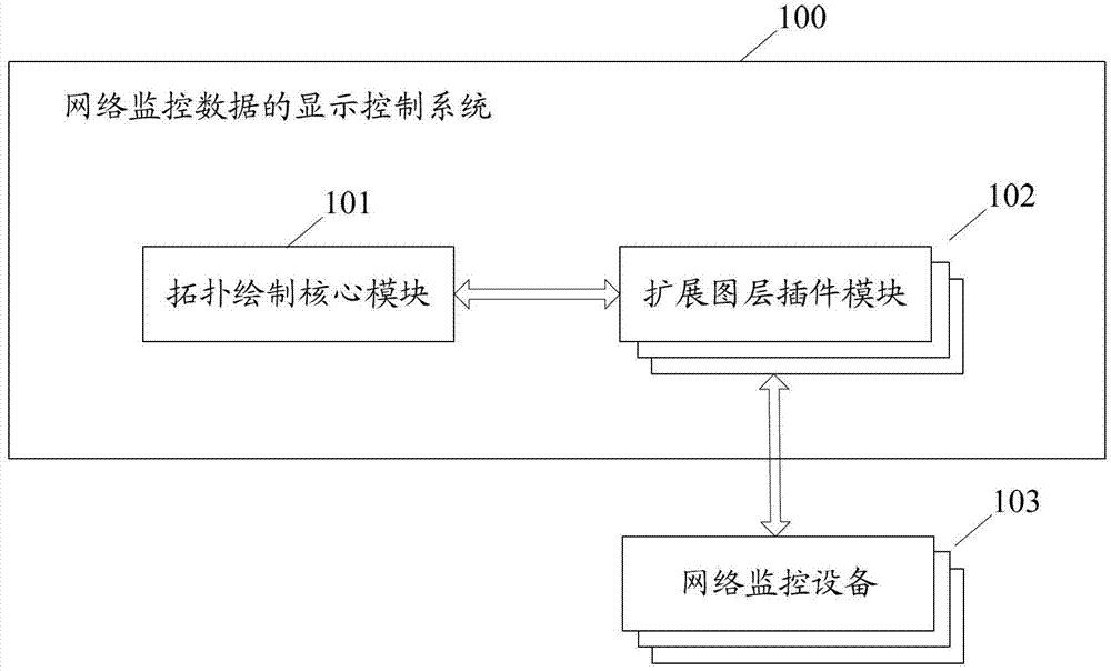
[0047] figure 1 A schematic diagram of the composition of the display control system of the network monitoring data of the present invention; see figure 1 , the display control system includes:

[0048] The topology drawing core module 101 is configured to obtain network topology data, draw a basic topology diagram according to the network topology data, and use the basic topology diagram as a basic layer to output and display it on a display device;

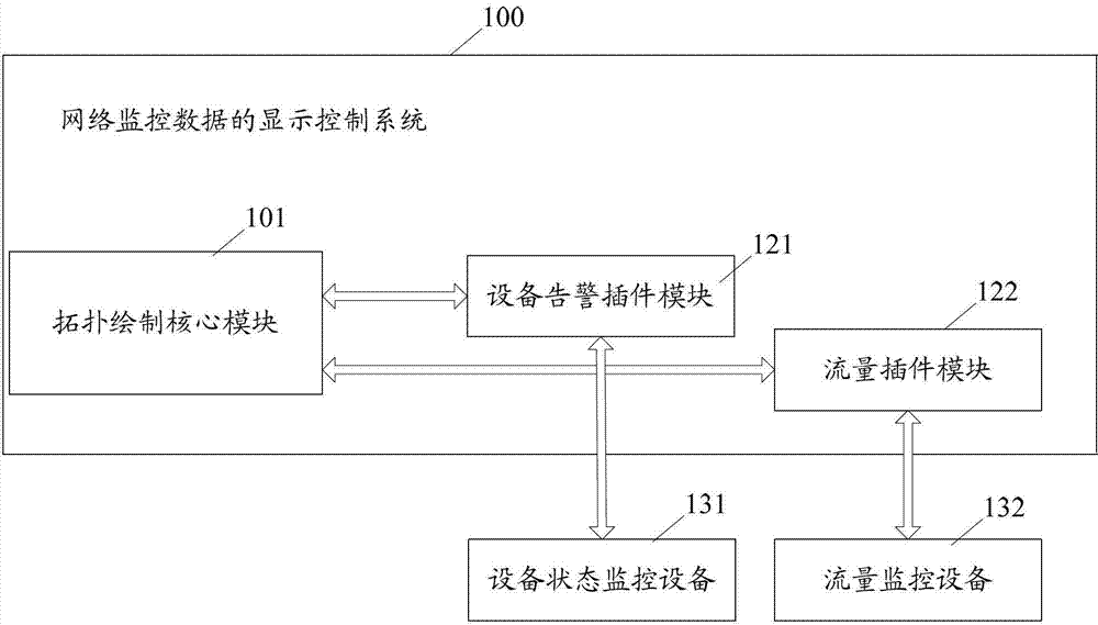
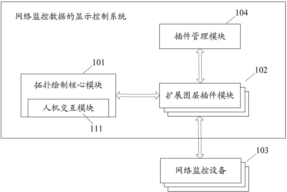
[0049] At least one extended layer plug-in module 102, configured to obtain network monitoring data corresponding to topological elements in the basic topology diagram from corresponding network monitoring devices 103; Extend the layer to obtain the position data of the topological element on the basic topological map, and draw a display icon corresponding to the network monitoring dat...


PUM


Abstract

The invention discloses a display control system and a display control method for network monitoring data. The display control method comprises the following steps that: a topological drawing core module acquires network topological data and draws a basic topological graph according to the network topological data; the basic topological graph is used as a basic layer; an expanded layer plug-in module is used for acquiring the network monitoring data corresponding to topological elements in the basic topological graph from network monitoring equipment; an expanded layer corresponding to the network monitoring data is constructed on the basic layer; position data of the topological elements on the basic topological graph; and display icons of the corresponding topological elements corresponding to the network monitoring data at the same position in the expanded layer. By the display control system and the display control method, the network monitoring data can be intuitively displayed in a graphical manner, and the flexibility and the expandability of a display control process and the customizability of displayed contents can be improved.

Description

technical field [0001] The present application relates to the technical field of communication network monitoring, and in particular to a display control system and method for network monitoring data. Background technique [0002] With the unprecedented development of information technology, the communication network has reached the point of pervasiveness, the network development has shown explosive growth, the small enterprise network has expanded to the medium enterprise network, the medium enterprise network has expanded to the large enterprise network, and the industry has also established different Backbone network, such as enterprise backbone network, government backbone network, etc. Therefore, the number of current network devices increases geometrically, and there are more and more network links. In this case, the biggest problem faced by network operators and network managers is the management of the communication network. Some devices and network links that users...

Claims


Application Information

Patent Timeline
IPC IPC(8): H04L12/26
Inventor 刘刚国吴飞
Owner MAIPU COMM TECH CO LTD
Learn More