Device for controlling a plurality of current breaking apparatuses via electric motors

A technology for current breaking and control devices, applied in the high-voltage field, which can solve problems such as bulky solutions, reliability problems, and high cost

Inactive Publication Date: 2013-02-13
ALSTOM TECH LTD
View PDF7 Cites 1 Cited by
  • Summary
  • Abstract
  • Description
  • Claims
  • Application Information

AI Technical Summary

Problems solved by technology

[0015] Most of the above documents only show electronic circuits dedicated to only one motor, and multiplying those circuits by the number of motors to be controlled leads to a particularly expensive and bulky

Method used


Image

  • Device for controlling a plurality of current breaking apparatuses via electric motors
  • Device for controlling a plurality of current breaking apparatuses via electric motors
  • Device for controlling a plurality of current breaking apparatuses via electric motors

Examples


Embodiment Construction

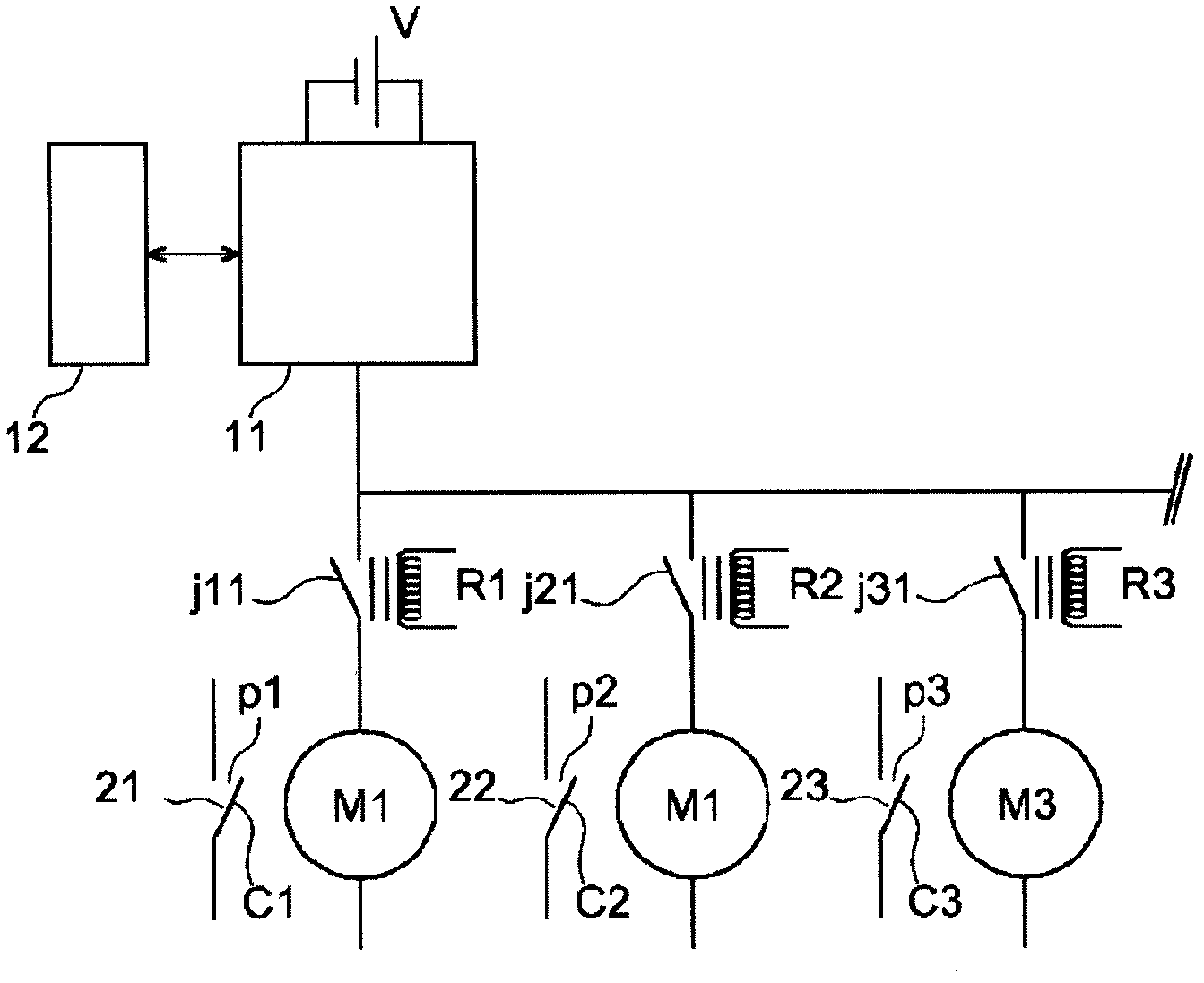
[0041] figure 2 is a single line schematic diagram of an arrangement for controlling a set of current breaking devices 21, 22, 23 in the same compartment of a high voltage substation. Three current breaking devices 21, 22, 23 are shown. It may be, for example, a disconnect switch or a circuit breaker. Each comprises at least one pair of electrical contacts P1, P2, P3, of which at least one electrical contact c1, c2, c3 is movable. The pair of electrical contacts P1, P2, P3 can be in an open position or a closed position. Accordingly, the respective current breaking device 21, 22, 23 is open or closed. An electric motor M1 , M2 , M3 is provided for mechanically actuating a movable contact c1 , c2 , c3 of the pair of electrical contacts P1 , P2 , P3 to urge it from an open position to a closed position or vice versa. There are as many electric motors M1 , M2 , M3 as there are current breaking devices 21 , 22 , 23 to be controlled. These electric motors M1, M2, M3 are prefe...


PUM


Abstract

The invention relates to a device for controlling a group of current breaking apparatuses (21, 22) via, for each current breaking apparatus, an actuation motor (M1, M2) which actuates at least one electrical contact of the current breaking apparatus. Said device comprises a single changeover contactor (11) controlled by control means (12) for connection to a power source (V) for the motors, and connected to the motors via switching means (R1, R2) for a current originating from the power source (V) and flowing through the changeover contactor (11). The invention is used for the control of current breaking apparatuses of a switch bay of a high-voltage electrical station.

Description

technical field [0001] The present invention relates to the field of high voltages and more particularly to the control of current breaking devices for connecting and disconnecting parts of a power grid. [0002] These devices may be circuit breakers with the function of protecting the power network, disconnectors or safety earthing switches with the function of isolating the circuit breaker or other device, line section so that operators can safely access it. In a three-phase system, these current breaking devices include three pairs of electrical contacts, each pair including at least one movable electrical contact that is actuated when closing or opening a pair of electrical contacts. Closing or opening these electrical contacts closes or opens the electrical circuit that includes these devices. Actuation is achieved by an electric motor operating the movable contacts of all pairs of identical current breaking devices. Only one current breaking device is assisted per moto...

Claims


Application Information

Patent Timeline
IPC IPC(8): H01H33/36H01H51/00
CPCH01H51/005H01H33/36
Inventor 帕特里斯·朱热纪尧姆·格拉内利让·吕克·拉永
Owner ALSTOM TECH LTD
Why Eureka
Try Eureka