
User-defined printing device

A custom and printing technology, applied in printing, printing machines, transfer printing, etc., can solve the problems affecting the aesthetics of clothing and changes in the shape of clothing, and achieve the effect of satisfying randomness and maintaining aesthetics

Inactive Publication Date: 2015-03-11
SUZHOU AORAN COMMODITY
View PDF8 Cites 0 Cited by
  • Summary
  • Abstract
  • Description
  • Claims
  • Application Information

AI Technical Summary

Problems solved by technology

[0003] In heat transfer, the pigment is first printed on the paper by printing method to make transfer printing paper, and then the color is transferred to the fabric through high temperature (heating and pressing on the back of the paper). It is generally used for chemical fiber fabrics and is characterized by bright colors. , delicate layers, realistic patterns, and strong artistry, but this process is currently only applicable to a few synthetic fibers such as polyester
The transfer printing process is simple, the investment is small, and the production is flexible. It is currently popular in the market. This printing method greatly meets the individual needs of consumers, but the individualization brings the improvement of the printing process. Printing in a defined way, so the distribution of printing positions is different. Ordinary heat press machines only roughly press the entire platen on the clothing to be printed, resulting in changes in the shape of the clothing and affecting the aesthetics of the clothing.

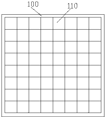
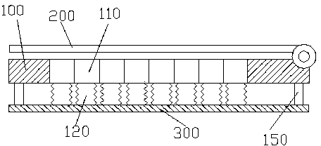
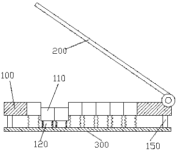
Method used


Image

  • User-defined printing device
  • User-defined printing device
  • User-defined printing device

Examples


Embodiment Construction

[0014] Below in conjunction with accompanying drawing and embodiment the present invention is further described:

[0015] refer to figure 1 , figure 2 , in this embodiment, the custom printing device includes an upper platen 200 and a lower platen 100, the upper platen 200 is a touch screen, the touch screen 200 is hinged to one side of the lower platen 100, and the lower platen 100 includes a row Square pressing blocks 110 in a rectangular array and a rectangular frame for accommodating the rectangular array, the square pressing blocks 110 are movably connected to each other, that is, the square pressing blocks 110 can move up and down on the plane of the lower pressing plate 100, The bottom of the lower platen 100 is fixed with a base plate 300 through the column 150, and the air column 120 corresponding to the square briquetting block 110 is evenly distributed on the base plate 300, and the air column 120 is connected to the corresponding square briquetting block 110. , ...


PUM


Abstract

The invention provides a user-defined printing device. The device comprises an upper pressing plate and a lower pressing plate, wherein the upper pressing plate is a touch screen, the touch screen is hinged with one side of the lower pressing plate, the lower pressing plate comprises square pressing blocks and a rectangular frame, square pressing blocks are arranged in a rectangular array, the rectangular frame contains the rectangular array, square pressing blocks are connected with one another in a moving mode, a base plate is fixed below the lower pressing plate through an upright post, gas columns corresponding to square pressing blocks are evenly distributed on the base plate and are connected with corresponding square pressing blocks, solenoid valves are arranged on gas columns and are connected with an air pump, and solenoid valves, the touch screen and a control module are connected electrically. According to the user-defined printing device, areas of clothes, which are to be printed, can be selected visually through the touch screen, so that individual requirements of users can be met.

Description

technical field [0001] The invention relates to the field of textile printing equipment, in particular, a printing device for customizing printing parts. Background technique [0002] The heat press machine can heat various heat transfers on cotton, linen, chemical fiber and other fabrics, and can also perform heat treatment such as screen printing, glue, foaming, etc., and can also print color codes, portrait photos, Landscape patterns are baked on porcelain plates and metal plates, especially suitable for making medals, commemorative badges, cultural shirts, etc., economical and practical, with exquisite patterns. It is replacing traditional embroidery and screen printing, but the cost and effect are much lower and better than general embroidery and multi-color screen printing. And time, the layer on the transfer paper and heat-set bond to the substrate or penetrate into the substrate. [0003] In heat transfer, the pigment is first printed on the paper by printing metho...

Claims


Application Information

Patent Timeline
Patent Type & Authority Patents(China)
IPC IPC(8): B41F16/02
Inventor 石东来
Owner SUZHOU AORAN COMMODITY
Learn More