Glass bottle opening inner plug capping machine

A capping machine and glass bottle technology, applied in the direction of bottle/container cap, closure plug, bottle filling, etc., can solve the problems of high labor intensity, broken glass bottle mouth, high labor cost, etc., and achieve reasonable structural design and high quality stoppering The effect of stability and high stoppering efficiency

Active Publication Date: 2013-02-27
常州市金坛晨光轻工机械有限公司
View PDF10 Cites 12 Cited by
  • Summary
  • Abstract
  • Description
  • Claims
  • Application Information

AI Technical Summary

Problems solved by technology

At present, in the field of bottle packaging, there is no special equipment for adding inner plugs to the glass bottle mouths. The process of adding inner plugs to the glass bottle mouths is all done manually. The conveyor belt is automatically conveyed, and the inner stopper station and the inner stopper station are added on the conveying line. One person places the inner stopper at the bottle mouth, the stopper worker places the inner stopper on the bottle mouth, and the other person is dedicated to pressing the stopper. The cork worker uses a rubber hammer to knock the inner plug placed on the bottle mouth and press it into the bottle mouth. Using this method of adding inner plug not only has low operating efficiency and high labor intensity, but also during the corking process, the corking worker's knock The pressing force must be controlled accurately, the inner plug cannot be pressed into the bottle mouth if the force is too small, and the glass bottle mouth will be broken if the force is too large
Due to the rising labor cost in our country, the traditional Ganeser scheme not only cannot guarantee the quality, but also has too many human influence factors, and the labor intensity is too high, and the labor cost is too high

Method used


Image

  • Glass bottle opening inner plug capping machine
  • Glass bottle opening inner plug capping machine
  • Glass bottle opening inner plug capping machine

Examples


specific Embodiment approach

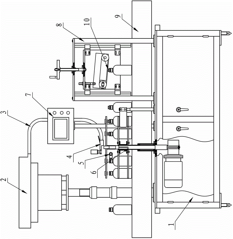
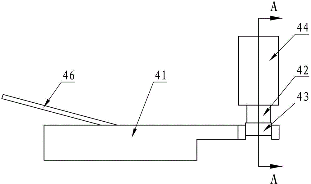
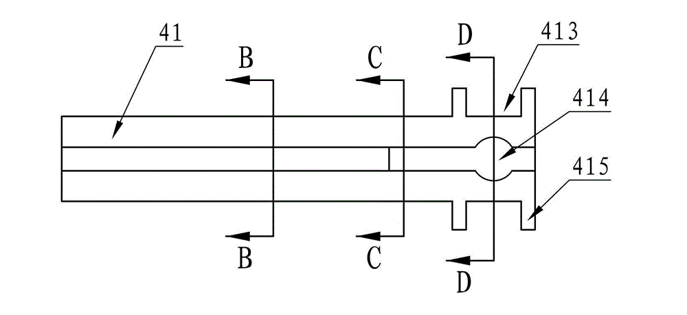
[0023] A glass bottle mouth stopper capping machine, such as Figure 1~Figure 13As shown, it includes a frame 1, a cap unscrambling device 2, a lower cork groove 3, a guide cork drop mechanism 4, a bottle inspection photoelectric sensor 5, a bottle pulling guide mechanism 6, an operation touch screen 7, a cork pressing mechanism 8 and a bottle conveying belt 9, The cap sorting device 2 is fixedly installed on the frame 1, and the lower plug groove 3 is arranged between the cap sorting device 2 and the guide plug drop mechanism 4. One end of the lower plug groove 3 communicates with the cap sorting device 2, and the other end connects with the guide drop mechanism 4. The plug mechanism 4 is connected, and the guide plug drop mechanism 4 is arranged on the top of the bottle-pushing guide mechanism 6. The guide plug drop mechanism 4 includes a body 41, a piston guide sleeve 42, a lower plug movable stopper 43, a plug push cylinder 44, and a stopper. The block pin 45 and the air b...


PUM


Abstract

The invention relates to a glass bottle opening inner plug capping machine. The glass bottle opening inner plug capping machine comprises a stand, a cap sorter, a plug feeding groove, a guide plug falling mechanism, a bottle inspection photoelectric sensor, a bottle shifting guide mechanism, an operation touch screen, a plug pressing mechanism and a bottle conveying belt, wherein the plug feeding groove is arranged between the cap sorter and the guide plug blanking mechanism; the guide plug falling mechanism is arranged above the bottle shifting guide mechanism; the bottle inspection photoelectric sensor is mounted at the bottle inlet end of the bottle shifting guide mechanism; the plug pressing mechanism is arranged on both sides of the bottle conveying belt and positioned behind the bottle shifting guide mechanism; and the cap sorter, the guide plug falling mechanism, the bottle inspection photoelectric sensor, the bottle shifting guide mechanism, the operation touch screen, the plug pressing mechanism and the bottle conveying belt are arranged on the stand. The glass bottle opening inner plug capping machine is reasonable in structural design. Plugs can be sorted, conveyed, fallen and pressed automatically, the plugging efficiency is high, plug pressing is stable, the phenomenon that a bottle opening is crushed is avoided, the whole plugging process does not need manpower, and the plugging quality is stable without influence by human factor.

Description

Technical field: [0001] The invention relates to a filling production equipment, in particular to an equipment for adding a cap and an inner plug to the mouth of a glass bottle. Background technique: [0002] In the liquid filling industries such as pesticides, medicines, cosmetics, food, beverages, and wines, it is very common to use glass bottles as packaging. In order to ensure the sealing of the bottle mouth, the most reliable solution is to add a rubber inner plug to the bottle mouth. With the modern The development of industry requires more and more items to be sealed and packaged in glass bottles. At present, in the field of bottle packaging, there is no special equipment for adding inner plugs to the glass bottle mouths. The process of adding inner plugs to the glass bottle mouths is all done manually. The conveyor belt is automatically conveyed, and the inner stopper station and the inner stopper station are added on the conveying line. One person places the inner ...

Claims


Application Information

Patent Timeline
Patent Type & Authority Applications(China)
IPC IPC(8): B67B1/00
Inventor 眭小平李卫庆
Owner 常州市金坛晨光轻工机械有限公司
Why Eureka
Try Eureka