Meteor crater detecting method based on bright and dark area pairing

A detection method and crater technology, applied in the field of image processing, can solve the problems of high mis-extraction rate and difficulty in detecting irregular shapes, etc., achieve high real-time performance and improve the accuracy rate

Inactive Publication Date: 2013-02-27
HARBIN INST OF TECH
View PDF2 Cites 10 Cited by
  • Summary
  • Abstract
  • Description
  • Claims
  • Application Information

AI Technical Summary

Problems solved by technology

[0006] The purpose of the present invention is to solve the problems of high mis-extraction rate and difficulty in detecting irregularly shaped craters in the crater extractio

Method used


Image

  • Meteor crater detecting method based on bright and dark area pairing
  • Meteor crater detecting method based on bright and dark area pairing
  • Meteor crater detecting method based on bright and dark area pairing

Examples


specific Embodiment approach 1

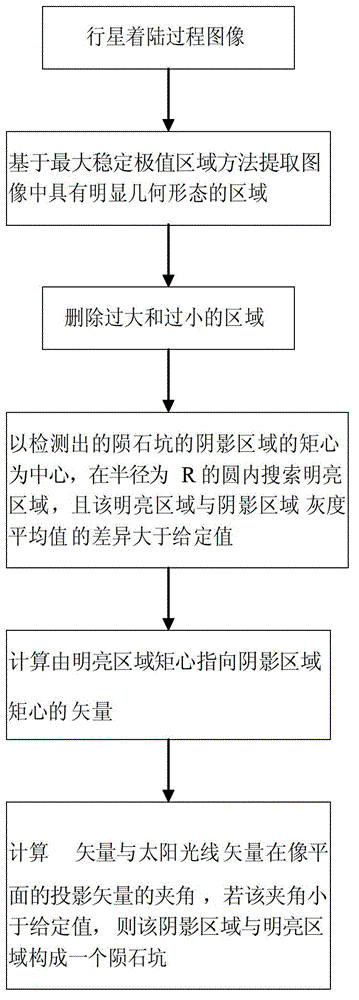
[0022] Specific embodiment one: the crater detection method based on light and dark area pairing of the present embodiment, the steps are as follows:

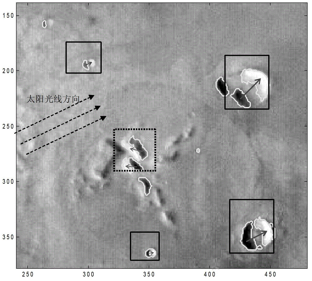
[0023] Step 1: Use the method of maximum stable extremum area to conduct preliminary detection on the image taken by the optical camera during the landing process of the planetary lander, and extract the shadow area and bright area in the image;

[0024] Step 2: Delete the areas of K and M in the shadow area and bright area extracted in step 1, and obtain n shadow areas D formed by light 1 、D 2 …D n and m bright regions L 1 , L 2 …L m , where n and m are natural numbers;

[0025] Step 3: Calculate the k-th shaded area D among the n shaded areas in Step 2 k centroid of by As the center, search for bright areas in a circle with radius R, and find p bright areas, 0≤p≤m; among them, D k Indicates the kth shaded area, and the value of the subscript k is 1, 2...n;

[0026] Step 4: Among the p bright regions searched in st...

specific Embodiment approach 2

[0049] Specific implementation mode two: the difference between this implementation mode and specific implementation mode one is: the steps described in step three

[0050] R = 2.13 | D | ,

[0051] Among them, |D| represents the sum of the pixels contained in the shaded area D. Other steps and parameters are the same as those in Embodiment 1.

specific Embodiment approach 3

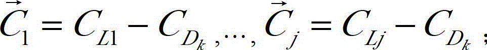
[0052] Specific implementation mode three: the difference between this implementation mode and specific implementation mode one or two is that: the steps described in step seven

[0053] θ 1 = arccos - 1 ( C → 1 · S → | C → 1 | · | S → | ) , · · · , θ j = arccos ...


PUM


Abstract

The invention discloses a meteor crater detecting method based on bright and dark area pairing, relates to the technical field of image processing, and aims to solve the problems that the conventional meteor crater extracting method based on a landmark navigation task in a planet landing section is high in mis-extraction rate and hard to detect irregular meteor craters, and the like. The method comprises the following steps of: carrying out primary detection on an image obtained by an optical camera during the planet landing process based on a maximum stable extreme value area method; extracting shadow areas and bright areas in the image; deleting overlarge or oversmall areas; taking the moment center of each detected shadow area of the meteor crater as the center; searching the bright areas within a circle with a R radius, wherein the difference of gray level average values of each bright area and each shadow area is larger than a given threshold; calculating a vector from the moment center of the shadow area to the moment center of each bright area; and calculating an included angle between the vector and a projection vector of a sunshine vector in a camera image plane, wherein if the value of the inclined angle is less than a given threshold, a meteor crater is formed by the shadow area and the bright area.

Description

technical field [0001] The invention relates to the technical field of image processing, in particular to a crater detection method based on light and dark region pairing. Background technique [0002] Meteor craters are ring-shaped depressions formed by small celestial bodies hitting the surface of a planet, and have unique geological forms. In planetary landing missions, craters can be used as navigation landmarks to improve the accuracy of the navigation system. Craters must be detected and extracted from images taken by the planetary lander's optical camera before navigational landmarks can be applied. The detection of craters is the basis for subsequent matching and navigation operations, and the detection results directly affect the performance of the navigation system. [0003] In planetary missions, extraction of craters can be used for autonomous navigation of the planetary landing segment. If the autonomous navigation mission of the planetary landing segment is ...

Claims


Application Information

Patent Timeline
IPC IPC(8): G01C11/04
Inventor 田阳崔祜涛徐田来余萌
Owner HARBIN INST OF TECH
Why Eureka
Try Eureka