
An online alignment device and online alignment method for fiber optic gyroscope modulation voltage

A fiber optic gyroscope and modulation voltage technology, which is applied to Sagnac effect gyroscopes and other directions, can solve the problems of modulation coefficient variation, inaccurate modulation voltage, and incompletely consistent modulation coefficients, and achieve the effect of accurate measurement.

Active Publication Date: 2016-01-20
武汉华中天勤防务技术有限公司
View PDF2 Cites 0 Cited by
  • Summary
  • Abstract
  • Description
  • Claims
  • Application Information

AI Technical Summary

Problems solved by technology

The problems with this measurement method are: ① The inherent phase difference of MIOC is ignored The phase difference with the Earth's rotational speed ②The modulation coefficients of MIOC are not exactly the same for different gyroscope light sources and sensitive loops; ③After the MIOC is fixed and packaged inside the fiber optic gyroscope, the modulation coefficient will be changed due to factors such as the deformation of the modulation electrode plate and the change of the temperature field distribution. ④Take the nominal value of the test as the standard, and the error of the test instrument will be brought into the gyro system, making the modulation voltage inaccurate

Method used


Image

  • An online alignment device and online alignment method for fiber optic gyroscope modulation voltage
  • An online alignment device and online alignment method for fiber optic gyroscope modulation voltage
  • An online alignment device and online alignment method for fiber optic gyroscope modulation voltage

Examples


Embodiment 1

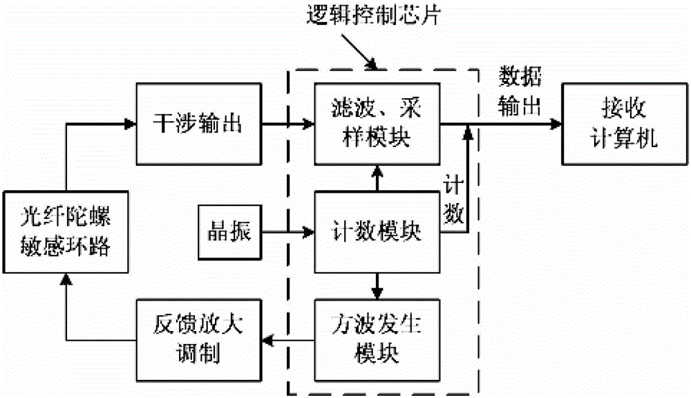
[0035] Example 1: As shown in appendix 1-4, it is an embodiment of an online alignment device of a fiber optic gyroscope modulation voltage of the present invention. The device includes a feedback amplification modulation unit connected to a fiber optic gyro sensitive loop, and a fiber optic gyroscope sensitive loop The connected interference output unit, the logic control chip connected with the feedback amplification modulation unit and the interference output unit, the crystal oscillator connected with the logic control chip, and the computer system connected with the logic control chip. The logic control chip includes a filtering and sampling module, a counting module, and a square wave generation module connected in sequence; the above-mentioned feedback amplification modulation unit is connected to the square wave generation module; the above-mentioned interference output unit is connected to the filtering and sampling module; The crystal oscillator is connected to the ...

Embodiment 2

[0036] Example 2: As shown in appendix 5, it is an embodiment of the online alignment method of fiber optic gyro modulation voltage with the device of the present invention. The steps of the method are as follows:

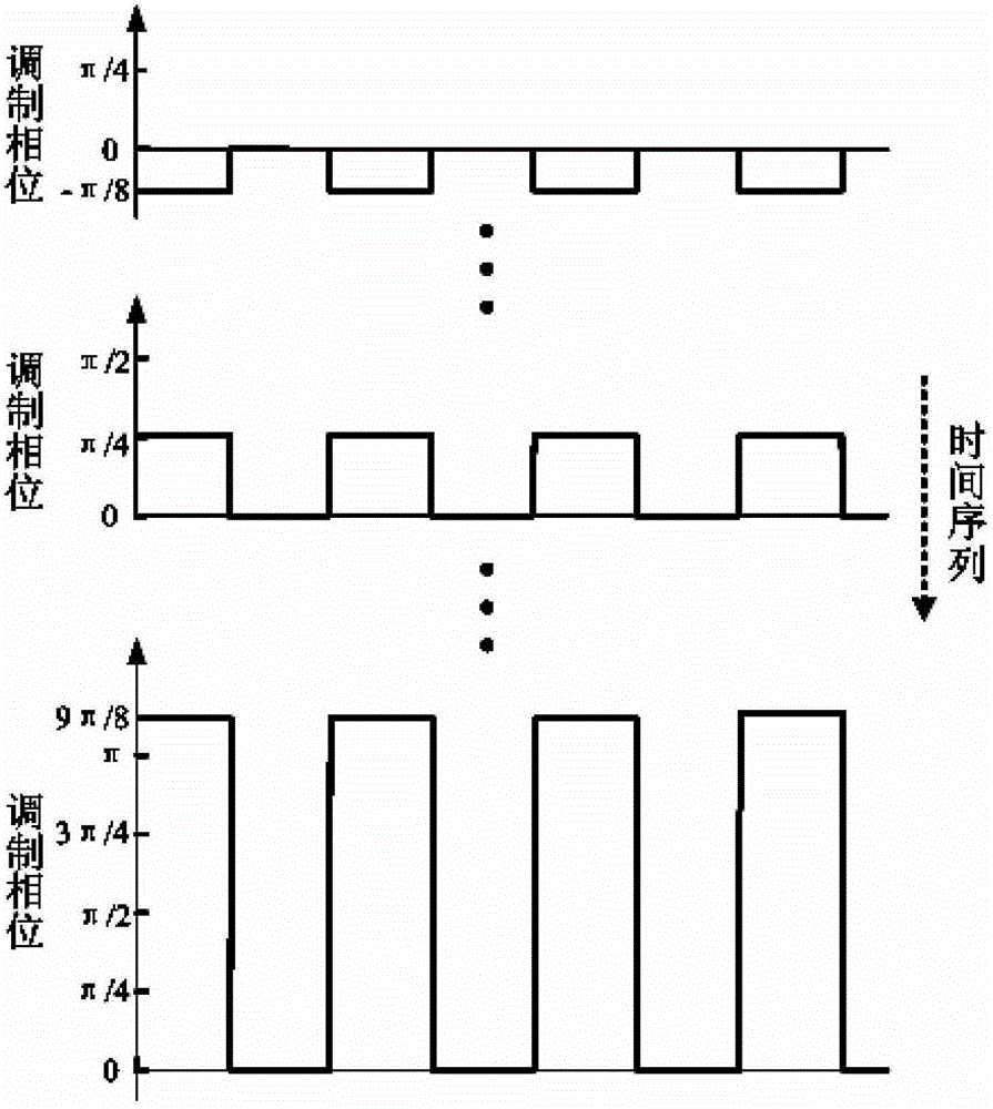
[0037] A. Generate step-wise modulated waveforms: program to realize the square wave generation module, and generate modulated waveforms whose amplitudes vary stepwise with time;

[0038] B. Optical fiber sensitive loop interference output: the modulation effect makes the optical fiber sensitive loop interference output a cosine response of the modulation amplitude;

[0039] C. Computer system receiving and processing: the computer system receives and processes the interference output, and locks the double extreme value area;

[0040] D. Generating slow and fine-changing modulation waveforms: for the locked area, generate modulation waveforms whose amplitudes slowly and finely change over time;

[0041] E. Optical fiber sensitive loop output: optical fiber sensi...


PUM


Abstract

The invention relates to an on-line alignment device and an on-line alignment method for optical fiber gyroscope modulation voltage. The crystal oscillator connected to the control chip, and the computer system connected to the logic control chip. The steps of the method include: A. generating step-wise modulated waveforms, B. optical fiber sensitive loop interference output, C. computer system receiving and processing, D. generating slow and finely changing modulated waveforms, E. optical fiber sensitive loop output, F. Computer system reception and judgment, and G. Modulation fine alignment. The advantages of the present invention are: it can precisely scan, lock and process the bipolar value of the sampled data, so as to achieve the purpose of precise alignment of the modulation voltage; it adopts the modulation voltage output mode of digital least significant bit accumulation, and the accuracy reaches the limit of the gyroscope when it is working .

Description

technical field [0001] The invention relates to an on-line alignment device and an on-line alignment method, in particular to an on-line alignment device and an on-line alignment method for optical fiber gyroscope modulation voltage. Background technique [0002] Compared with the traditional mechanical gyroscope, the fiber optic gyroscope has no moving parts, relatively simple structure, light weight, fast startup, high sensitivity, wide dynamic range, high reliability, and can directly use digital output. It is used in mobile carriers and military applications Very ideal. Compared with ring laser gyroscopes, fiber optic gyroscopes do not require high-precision processing of optical lenses, strict sealing of optical cavities, and mechanical biasing technology, which effectively overcomes the locking phenomenon of laser gyroscopes. As a new high-performance inertial instrument, fiber optic gyroscope represents the development direction of high-precision gyroscope in the fut...

Claims


Application Information

Patent Timeline
Patent Type & Authority Patents(China)
IPC IPC(8): G01C19/72
Inventor 张琛陆家兵黄根旺朱牡丹
Owner 武汉华中天勤防务技术有限公司
Learn More