Rotor for a camshaft adjuster and camshaft adjuster

A camshaft adjuster and rotor technology, which is applied in the direction of machines/engines, engine components, mechanical equipment, etc., can solve the problems of increasing costs and other issues

Inactive Publication Date: 2013-02-27
SCHAEFFLER TECH AG & CO KG
View PDF6 Cites 3 Cited by
  • Summary
  • Abstract
  • Description
  • Claims
  • Application Information

AI Technical Summary

Problems solved by technology

[0007] Although all the aforementioned embodiments for the rotor reduce the leakage inside the camshaft adjuster, the separate sealing element disadvantageously increases the production technically with additional outlay and further costs

Method used


Image

  • Rotor for a camshaft adjuster and camshaft adjuster
  • Rotor for a camshaft adjuster and camshaft adjuster

Examples


Embodiment Construction

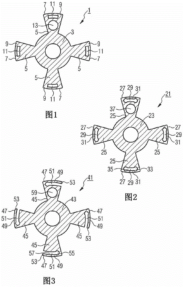
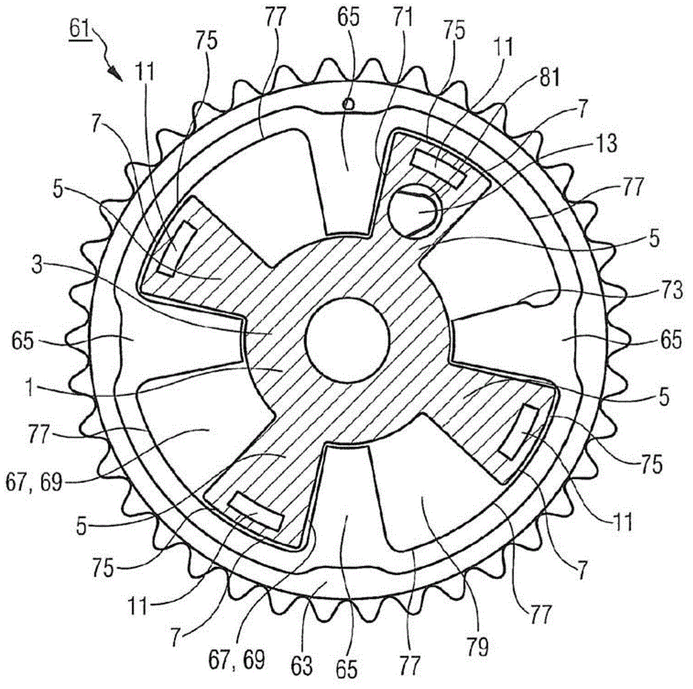
[0037] figure 1 The rotor 1 for a camshaft adjuster is shown in cross-section. The rotor 1 has a rotor base 3 with four rotor blades 5 extending radially outward. In the installed state, when the rotor 1 is positioned in the stator, the rotor blades 5 are used to divide each pressure chamber of the camshaft adjuster into two adjacent hydraulic regions. in Figure 4 The camshaft adjuster is shown in.

[0038] The rotor base 3 and the rotor blades 5 are integrally made of a metal material by a sintering method. Unlike the two-part manufacturing method in which the rotor blades 5 are held, for example, in grooves of the rotor base body 3, the possible leak locations are minimized by an integrated method. In addition, the sintering method provides the possibility of using an automated process flow, so it is cheap and easy to implement. Based on the dimensional accuracy of this method, the rotor 1 can be manufactured in such a way that the radial leakage gap between the blade end ...


PUM


Abstract

The invention relates to a rotor (1, 21, 41) for a camshaft adjuster (61), comprising a rotor base body (3, 23, 43) and a number of rotor blades (5, 25, 45) extending radially outwards and located on the rotor base body (3, 23, 43), each of said blades having a blade end (7, 27, 47). To reduce leakage, the blade ends (7, 27, 47) of the rotor blades (5, 25, 45) take the form of sealing fins (9, 31, 49) that can be deformed radially outwards. A rotor (1, 21, 41) of this type affords the possibility of reducing leakage in a camshaft adjuster (61) using simple engineering and without added costs. The invention also relates to a camshaft adjuster (61) for an internal combustion engine, comprising a rotor (1, 21, 41) of this type.

Description

Technical field [0001] The invention relates to a rotor for a camshaft adjuster, which has a rotor base and a certain number of rotor blades arranged on the rotor base and extending radially outward. In addition, the present invention also relates to a camshaft adjuster having such a rotor. Background technique [0002] The rotor is used to assist in the targeted adjustment of the phase between the camshaft and the crankshaft in the internal combustion engine. For this reason, it is usually held as part of the camshaft adjuster in a stator connected to the crankshaft in a torque-proof manner. In the installed state, the rotor is connected to the camshaft in a torque-proof manner and can be adjusted relative to the stator, so that the camshaft can rotate relative to the stator within a predetermined angular range. In this way, for example, the power of the internal combustion engine can be increased in a targeted manner or the fuel consumption of the internal combustion engine c...

Claims


Application Information

Patent Timeline
Patent Type & Authority Applications(China)
IPC IPC(8): F01L1/344
CPCF01L1/3442F01L1/356F01L2001/34479
Inventor 阿明·布劳恩
Owner SCHAEFFLER TECH AG & CO KG
Why Eureka
Try Eureka