Carbon dioxide catching device and method

A technology for carbon dioxide and capture devices, applied in chemical instruments and methods, separation methods, inorganic chemistry, etc., can solve problems such as blockage, consumption of more energy, corrosion of pipelines or storage tanks, etc., to achieve the effect of improving the purity of capture

Inactive Publication Date: 2013-03-06
JG ENVIRONMENTAL TECH +1
View PDF5 Cites 7 Cited by
  • Summary
  • Abstract
  • Description
  • Claims
  • Application Information

AI Technical Summary

Problems solved by technology

[0003] again, as figure 1 As shown, the applicant has developed a technology that can effectively capture carbon dioxide, which utilizes the adsorption material contained in the adsorption-desorption unit 10 to continuously adsorb the gas flow to be treated input by the gas flow input pipe 11 at low temperature (<80°C) carbon dioxide, and the treated gas flow is output from the treated gas flow output pipe 14, and then the desorption steam supply source 20 provides steam through the desorption steam input pipe 13, so as to concentrate and desorb the carbon dioxide adsorbed by the adsorbent and self-desorb The rear steam output pipe 16 is output; yet, although the concentration of the desorbed carbon dioxide can reach about 80%, the purity of the carbon dioxide for the follow-up storage procedure is very important, if it contains water vapor, sulfur-containing gas or chemical substances, then More energy must be consumed when pressurizing, and chemicals can also cause corrosion or blockage of pipelines or storage tanks, which cannot guarantee the safety and durability of storage over time

Method used


Image

  • Carbon dioxide catching device and method
  • Carbon dioxide catching device and method
  • Carbon dioxide catching device and method

Examples


no. 1 example

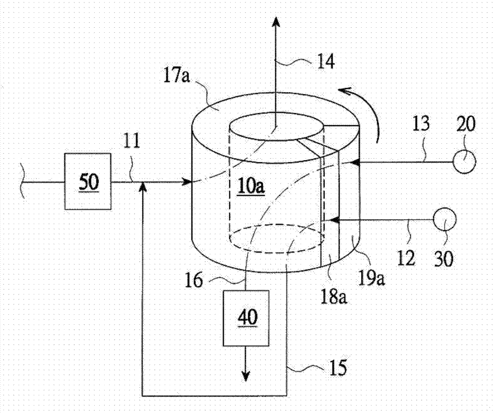
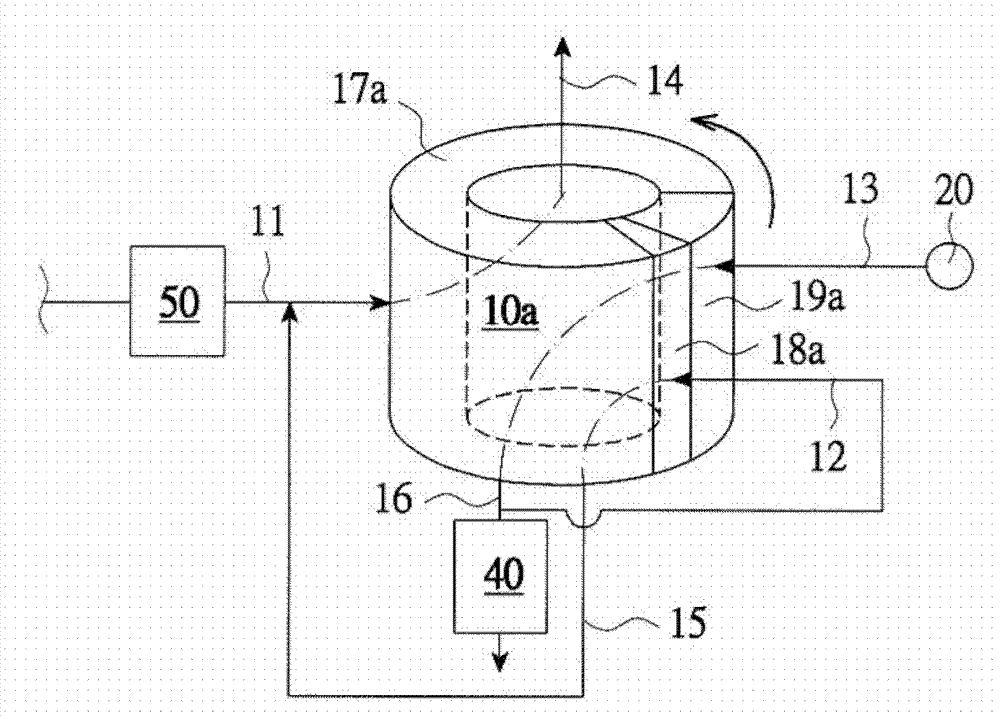
[0034] First, see Figure 2A , Figure 2B , Figure 2C As shown, the first embodiment of the present invention includes:

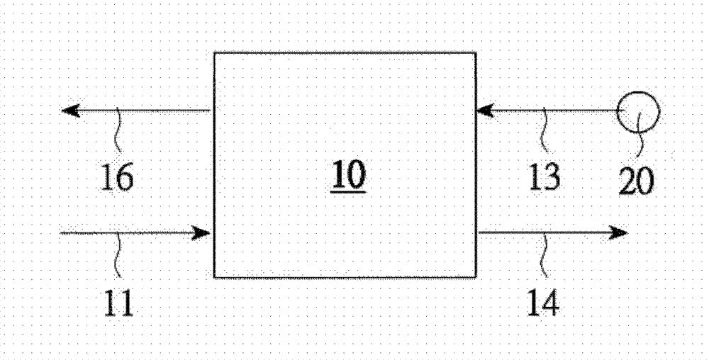
[0035] A swivel-type adsorption-desorber 10a has an adsorbent for absorbing carbon dioxide inside, and is externally connected with a gas flow input pipe 11 to be treated, a flushing gas flow input pipe 12, a desorption steam input pipe 13, and a treated gas flow output pipe. Pipe 14, an air flow output pipe 15 after flushing and a desorbed steam output pipe 16, and follow the direction of rotation to separate the adsorption area 17a, the washing area 18a and the desorption area 19a, and make the air flow to be treated input pipe 11 The treated gas flow output pipe 14 is oppositely connected to both sides of the adsorption area 17a, the flushing air flow input pipe 12 is connected to the both sides of the flushing area 18a oppositely to the washed air flow output pipe 15, and the desorption steam input pipe 13 is connected to the The desorbed steam outp...

no. 4 example

[0051] Alternatively, see Figure 5A , Figure 5B , Figure 5C As shown, the fourth embodiment of the present invention includes:

[0052] A fluidized bed adsorption-desorber 10d has an adsorption material for absorbing carbon dioxide inside, and is an adsorption bed 101, a desorption bed 102, and a delivery pipeline for circulating the adsorption material between the adsorption bed 101 and the desorption bed 102 103, the lower and upper sides of the adsorption bed 101 are connected to a gas flow input pipe 11 to be treated and a gas flow output pipe 14 to be treated, and the lower and upper sides of the desorption bed 102 are connected to a flushing gas flow The input pipe 12 and a flushed air flow output pipe 15 and a desorption steam input pipe 13 and a desorption steam output pipe 16;

[0053] The flushing air inlet pipe 12 is connected to a flushing air supply source 30 (such as Figure 5A shown), and the flushing airflow supply source 30 supplies the flushing airflow...


PUM


Abstract

The invention relates to a carbon dioxide catching device and a carbon dioxide catching method. The device comprises an absorption and desorption unit with an absorption material used for absorbing carbon dioxide arranged inside. An inlet pipe of gas flow to be treated, a flushing gas flow inlet pipe, a desorption steam inlet pipe, an outlet pipe of treated gas flow, an outlet pipe of flushed gas flow, and an outlet pipe of desorbed steam are connected on the outside of the absorption and desorption unit. The device also comprises a flushing gas flow supply unit used for supplying flushing gas flow to the absorption and desorption unit, and a desorption steam supply unit connected with the desorption steam inlet pipe. The method comprises the steps of: an absorption step in which carbon dioxide in gas flow to be treated is absorbed by using the absorption material; a flushing purification step in which the carbon dioxide absorbed by the absorption material is flushed by using the flushing gas flow, such that the purity of the absorbed dioxide is improved; and a desorption step in which the carbon dioxide absorbed by the absorption material and purified is desorbed by using the desorption gas flow. With the device and the method provided by the invention, carbon dioxide capturing purity can be improved.

Description

technical field [0001] The present invention relates to a carbon dioxide capture device and method, in particular to a method for flushing carbon dioxide and substances other than steam from the adsorption material by supplying steam or a flushing flow of carbon dioxide before desorbing carbon dioxide from the adsorption material by using desorption steam Come out, and design the carbon dioxide purification effect on the adsorbent. Background technique [0002] With the growing greenhouse effect, the Kyoto Protocol came into effect, and carbon dioxide capture and storage (CCS) technology was also evaluated by the United Nations IPCC in 2005 as one of the feasible methods, and there are numerous related documents and patents Enumeration, including the most commonly discussed wet absorption MEA method, dry adsorption method, thin film method, etc. [0003] again, as figure 1 As shown, the applicant has developed a technology that can effectively capture carbon dioxide, which...

Claims


Application Information

Patent Timeline
Patent Type & Authority Applications(China)
IPC IPC(8): B01D53/04B01D53/06B01D53/12B01D5/00C01B31/20C01B32/50
CPCY02C10/08Y02A50/20Y02C20/40Y02P20/151Y02P70/10
Inventor 张丰堂
Owner JG ENVIRONMENTAL TECH
Why Eureka
Try Eureka