
Casting die

A mold and die technology, applied in the field of casting molds, can solve problems such as unreasonable mold runner design, products not meeting inspection requirements, and narrow mold application range, achieving simple structure, reasonable runner design, and improving product qualification. rate effect

Inactive Publication Date: 2013-03-06
常州市晨光机械制造有限公司
View PDF0 Cites 1 Cited by
  • Summary
  • Abstract
  • Description
  • Claims
  • Application Information

AI Technical Summary

Problems solved by technology

Due to the unreasonable design of the mold runner, the thickness of the plate will be uneven during the manufacturing process, resulting in the product not meeting the inspection requirements
The fixed discharge width and its own gap at the discharge port lead to a narrower application range of the mold

Method used


Image

  • Casting die
  • Casting die
  • Casting die

Examples


Embodiment Construction

[0012] The present invention will now be further described in conjunction with the accompanying drawings and preferred embodiments. These drawings are all simplified schematic diagrams, which only illustrate the basic structure of the present invention in a schematic manner, so they only show the configurations related to the present invention.

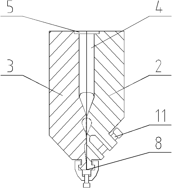
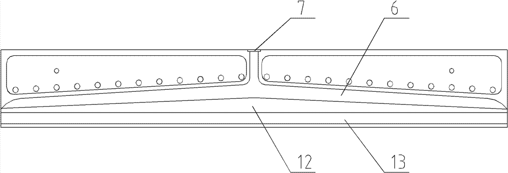
[0013] Such as figure 1 , figure 2 and image 3 A casting mold shown has an upper mold sheet 2 and a lower mold sheet 3 combined by sealing plates 1 arranged at both ends, and concave cavities are respectively arranged on the joint surfaces of the upper mold sheet 2 and the lower mold sheet 3 4 and the semicircular hole 5 communicating with the concave cavity 4, the concave cavity 4 after mold closing and combination forms a hanger-type flow channel 6, the semi-circular hole 5 forms a feed port 7 for raw materials to flow in, and the upper mold at the lower end of the hanger-type flow channel 6 The gap between the joint surfaces o...


PUM


Abstract

The invention discloses a casting die. The casting die comprises an upper die sheet and a lower die sheet which are combined through the die locking of seal plates arranged at two ends of the casting die; the faying surfaces of the upper die sheet and the lower die sheet are respectively provided with cavities and semi-circular orifices communicated with the cavities; after the die locking, the cavities form a hanger type channel, the semi-circular orifices form a material inlet for the flow-in of a raw material, and a gap between the faying surfaces of the upper die sheet and the lower die sheet at the lower end of the hanger type channel form a material outlet; two sides of the casting die at the material outlet are respectively provided with a die blocking buckle and a die blocking strip fixed on the material outlet through the die blocking buckle and adjusting the material discharge width; and the upper die sheet is provided with an adjustment screw which can adjust the self-gap of the material outlet. The casting device has the advantages of simple structure, reasonable channel design, product qualification rate improvement, adjustable material discharge width, adjustment of the self-gap of the material outlet, and enlargement of the die application range.

Description

technical field [0001] The invention relates to a casting mold. Background technique [0002] Currently used flat dies for extruding sheets generally include upper dies, lower dies and sealing plates at both ends. Due to the unreasonable design of the mold flow channel, the thickness of the plate will be uneven during the manufacturing process, resulting in the product not meeting the inspection requirements. The fixed discharge width and its own gap at the discharge port lead to a narrow application range of the mold. Contents of the invention [0003] The technical problem to be solved by the present invention is: to overcome the deficiencies in the prior art, to provide a casting die, the runner design is reasonable, the thickness of the produced plate can be made uniform, and the discharge width and the self-gap of the discharge port can be adjusted , to expand the scope of application of the mold. [0004] The technical solution adopted by the present invention to ...

Claims


Application Information

Patent Timeline
Patent Type & Authority Applications(China)
IPC IPC(8): B29C47/16B29C48/31
Inventor 魏建民
Owner 常州市晨光机械制造有限公司
Learn More