Supercharge Your Innovation With Domain-Expert AI Agents!

Control unit of motor vehicle and method to operate motor vehicle

A technology for control devices and motor vehicles, applied in transmission control, mechanical equipment, vehicle parts, etc., can solve problems such as damage to switching elements, and achieve the effect of avoiding damage

Active Publication Date: 2013-03-06
ZF FRIEDRICHSHAFEN AG
View PDF8 Cites 5 Cited by
  • Summary
  • Abstract
  • Description
  • Claims
  • Application Information

AI Technical Summary

Problems solved by technology

Conversely, large rotational speed differences can lead to damage to the form-fitting switching element

Method used


Image

  • Control unit of motor vehicle and method to operate motor vehicle
  • Control unit of motor vehicle and method to operate motor vehicle

Examples


Embodiment Construction

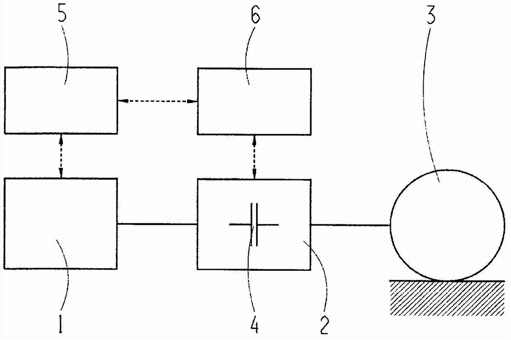
[0014] figure 1 A simplified diagram of the powertrain of a motor vehicle is shown schematically on a large scale. Therefore according to figure 1 The motor vehicle has a drive assembly 1 , a transmission 2 and a driven end 3 , wherein the transmission 2 is connected between the drive assembly 1 and the driven end 3 .

[0015] The transmission 2 comprises at least one form-fitting shifting element 4 , which can be realized, for example, as a pawl and has a drive-side component and an output-side component.

[0016] also figure 1 An engine control unit 5 for controlling and / or regulating the operation of the drive assembly 1 and a transmission control unit 6 for controlling and / or regulating the operation of the transmission 2 are shown. The engine control unit 5 exchanges data with the drive unit 1 in the direction of the double arrow. Likewise, the transmission control unit 6 exchanges data with the transmission 2 . Furthermore, data exchange takes place between the engi...


PUM


Abstract

The invention relates to a control unit of a motor vehicle. The control unit of a motor vehicle for activating a form-locking shift element of a transmission of the motor vehicle in such a way that a defined rotational speed difference is defined, between an input-side component of the form-locking shift element and an output-side component of the form-locking shift element, in order to engage the form-locking shift element. The control unit monitors the rotational speed gradient of the rotational speed of the output-side component of the form-locking shift element from an activation time of the form-locking shift element, at which the engagement process of the form-locking shift element begins. The control unit generates a control signal for a drive assembly in order to increase the torque, at a drive assembly, in the event that the control unit determines that the monitored rotational speed gradient falls below a lower limit. The invention also relates to a method to operate the motor vehicle.

Description

technical field [0001] The invention relates to a control device for a motor vehicle. Furthermore, the invention relates to a method for operating a motor vehicle. Background technique [0002] Motor vehicles are known in practice with transmissions having form-fitting shift elements and / or friction-locking shift elements. In the case of a friction-locking shift element, a relatively large rotational speed difference can exist between the drive-side component and the output-side component of the friction-lock shift element when closing the friction-lock shift element, so that The rotational speed difference can be reduced by the frictional power at the frictionally engaged shifting element. Conversely, closing the form-fitting shift element requires that a relatively small defined rotational speed difference be maintained between the drive-side component and the output-side component of the form-fitting shifting element. The specified rotational speed difference typically...

Claims


Application Information

Patent Timeline
Patent Type & Authority Applications(China)
IPC IPC(8): B60W30/18B60W10/04B60W10/10F16H61/02F16H63/50F16H61/68
CPCF16H2061/0474B60W30/19B60W2710/0666F16H61/04F16H63/502B60Y2400/421
Inventor J·魏勒
Owner ZF FRIEDRICHSHAFEN AG
Features
  • R&D
  • Intellectual Property
  • Life Sciences
  • Materials
  • Tech Scout
  • Unparalleled Data Quality
  • Higher Quality Content
  • 60% Fewer Hallucinations
Learn More