Floating scroll compressor

A scroll compressor and moving scroll technology, applied in the field of scroll compressors, can solve problems such as small space, tooth side leakage, and complex pressure chamber structure, and achieve the effect of large selection and simple structural design

Active Publication Date: 2013-03-06
冰山松洋压缩机(大连)有限公司
View PDF7 Cites 7 Cited by
  • Summary
  • Abstract
  • Description
  • Claims
  • Application Information

AI Technical Summary

Problems solved by technology

[0004] The disadvantage of the existing technology is that although the problem of tooth top leakage between adjacent compression chambers has been solved to a certain extent, the structure of the annular intermediate pr

Method used


Image

  • Floating scroll compressor
  • Floating scroll compressor
  • Floating scroll compressor

Examples


Embodiment 1

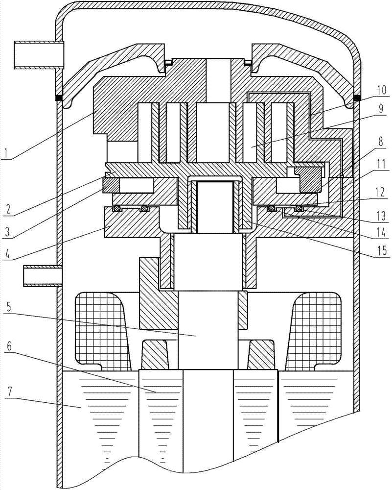
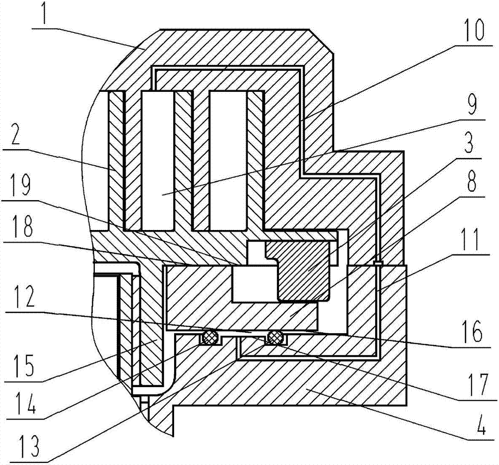
[0032] Such as figure 2As shown, a floating disc 8 is provided between the movable scroll 2 and the upper support 4, and the upper surface 17 of the upper support is provided with two annular grooves, and the seal A13 and the seal B14 are placed in the annular grooves, and the upper surface 17 of the upper support , the bottom surface of the floating plate 16, the seal A13 and the seal B14 form an annular pressure chamber A12, the pressure chamber A12 communicates with the upper support pressure introduction channel 11, and the other port of the upper support pressure introduction channel 11 is connected to the fixed scroll 1. The scroll pressure induction passage A10 communicates on the contact surface between the fixed scroll 1 and the upper support 4 , and the other port of the fixed scroll pressure introduction passage A10 communicates with the compression chamber 9 formed by the cooperation between the movable scroll 2 and the fixed scroll 1 .

Embodiment 2

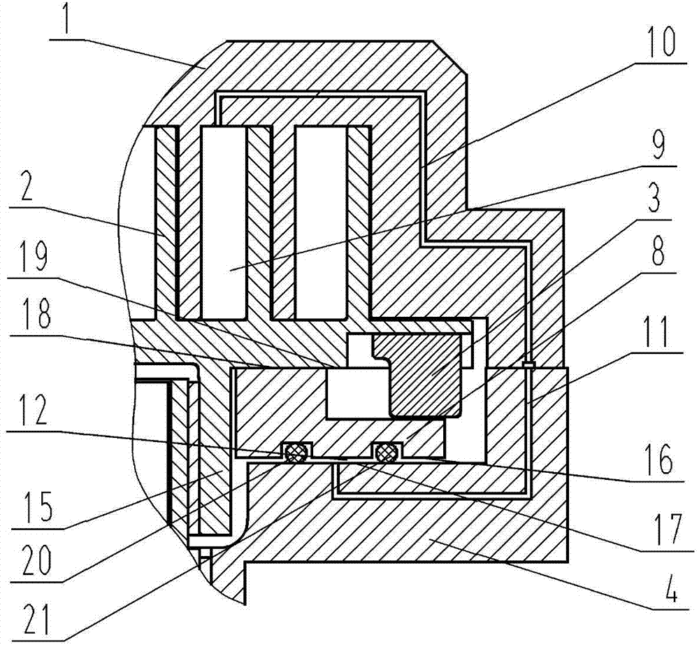
[0034] image 3 An embodiment of another sealing structure between the floating plate 8 and the upper support 4 is given, and its structure is as follows image 3 As shown: a floating disc 8 is provided between the movable scroll 2 and the upper support 4, and the bottom surface 16 of the floating disc is provided with two annular grooves, and the seal C20 and the seal D21 are placed in the annular grooves, and the upper surface of the upper support 17, An annular pressure chamber A12 is formed between the bottom surface 16 of the floating plate, the sealing member C20 and the sealing member D21.

Embodiment 3

[0036] Figure 4 An example of another opening form of the pressure introduction channel in the pressure chamber A12 is given, and its structure is as follows Figure 4 As shown: the pressure chamber A12 is connected to the upper support pressure introduction channel 11, and the other port of the upper support pressure introduction channel 11 and the fixed scroll pressure introduction channel B22 on the fixed scroll 1 are on the contact surface between the fixed scroll 1 and the upper support 4 The other port of the fixed scroll pressure guiding channel B22 communicates with the high pressure chamber 23 of the compressor.


PUM


Abstract

The invention discloses a floating scroll compressor. The floating scroll compressor comprises a fixed scroll, a movable scroll, a cross ring, an upper support, a crankshaft, a motor rotor, a motor stator and a floating disk which are arranged in a compressor casing, wherein the floating disk is arranged between the movable scroll and the upper support; an annular pressure chamber is arranged between the bottom surface of the floating disk and the upper surface of the upper support; the floating disk moves along the movable scroll; and a pressure enclosing channel communicated with a compression chamber or a high-pressure chamber is arranged in the annular pressure chamber. The floating scroll compressor disclosed by the invention has the beneficial effects that the pressure chamber is sealed by a sealing element; the structural design is simple and the sealing element is wide in selective range; in the starting process of the compressor, a starting load can be reduced; and the floating disk and the movable scroll move together, so that the reducing effect of the radial distance is remarkable and the tooth side leakage is remarkably reduced.

Description

technical field [0001] The invention belongs to the field of scroll compressors, in particular to a scroll compressor tooth top and tooth side sealing structure. Background technique [0002] The existing scroll compressor includes a fixed scroll with a spiral scroll, a movable scroll with a spiral spiral matched with the fixed scroll, and a moving scroll between the movable scroll and the upper support. The Oldham ring, the Oldham ring cooperates with the movable and fixed scrolls respectively and restricts them to be relatively translational. Through the mutual cooperation of the movable scroll and the fixed scroll, multiple compression chambers with variable volume are formed, which are driven by the crankshaft driven by the motor. The movable scroll revolves along its orbit to complete the suction, compression and discharge of gas. In order to improve the efficiency, it is necessary to make the volute crests of the two volutes fit closely with the tooth bottoms of the o...

Claims


Application Information

Patent Timeline
IPC IPC(8): F04C18/02F04C29/00F04C27/00
Inventor 王伟周英涛刘忠赏
Owner 冰山松洋压缩机(大连)有限公司
Why Eureka
Try Eureka