Leakage remedying device of steam straight buried pipe compensator

A technology of compensators and direct-buried pipes, which is applied in the direction of pipe components, pipes/pipe joints/fittings, mechanical equipment, etc., which can solve the problems of easy damage of compensation devices, waste of energy and resources, and impact on city appearance, so as to reduce excavation Quantity, reducing maintenance time, saving maintenance and construction costs

Active Publication Date: 2013-03-06
淮安四方保温管有限公司
View PDF6 Cites 2 Cited by
  • Summary
  • Abstract
  • Description
  • Claims
  • Application Information

AI Technical Summary

Problems solved by technology

[0003] At present, there are many forms of compensation devices on the market, among which the bellows type compensation device is widely used, but no matter what kind of compensation device it is, there is a common problem: due to the frequent operation of the compensation device, it is very easy to be damaged, when the compensation device After damage, the high-temperature and high-pressure steam breaks through the insulation layer of the core tube, and then rushes out from the observation tube of the outer protective tube
If high-temperature and high-pressure steam accumulates in the outer protective tube, the high temperature will cause the glass fiber reinforced plastic resin wrapped on the outer surface of the outer protective tube to melt, and the outer protective tube will lose its anti-corrosion function
[0004] Since the compensation device is buried in the ground along with the heat pipeline, maintenance workers cannot determine the location of its damage, so targeted construction cannot be carried out, and it can only be allowed to develop
It can be seen from the above that the damage of the compensation device not only affects the appearance of the city, but more importantly wastes a lot of energy and resources.

Method used


Image

  • Leakage remedying device of steam straight buried pipe compensator

Examples


Embodiment Construction

[0022] The present invention will be further described below in conjunction with the accompanying drawings and embodiments, which are only used to explain the present invention and do not constitute a limitation to the protection scope of the present invention.

[0023] In this embodiment, the compensator is a bellows type compensator, and the outer protection tube is not marked in the drawings.

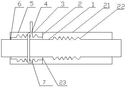
[0024] like figure 1 As shown, the steam direct buried pipe compensator leakage remedial device includes a core tube 1 arranged in the outer protective tube, and a compensator 2 sleeved on the core tube 1, and one end of the protective sleeve 21 of the compensator 2 is connected to the core tube 1 is provided with an A gap 23, and on the core tube 1 at the end where the protective cover 21 and the core tube 1 are provided with the A gap 23, a remedial device is set on the same circle center, and the A gap 23 communicates with the remedial device, so The remedial device is provided ...


PUM


Abstract

The invention provides a leakage remedying device of a steam straight buried pipe compensator, which comprises a core pipe arranged outside an external protective pipe; and a remedying device is sleeved centrically on the core pipe on one end of the core pipe, where a gap is formed between the protective sleeve and the core pipe. The remedying device comprises a protective cover and a corrugated pipe orderly arranged from outside to inside, wherein the same ends of the protective cover and the corrugated pipe are hermetically connected to the protective sleeve; a gap is arranged between the other end of the protective cover and the core pipe. A steam discharge pipe is communicated to the corrugated pipe and penetrates to a hole arranged by the protective cover and the external protective pipe outwards. The leakage remedying device has the following advantages: avoiding the steam in the damaged compensator impacting and destroying a heat insulation layer, and the leaked steam condensate water soaking heat insulation cotton; avoiding the steam that the compensator leaks accumulating in the external protective pipe and reducing the useful life of the pipeline; ensuring normal flexibility and deformation of the core pipe; being convenient to maintain specifically; reducing maintenance time and reducing earth excavating volume.

Description

technical field [0001] The invention relates to the technical field of steam pipelines, in particular to a leakage remedy device for directly buried steam pipeline compensators. Background technique [0002] In the process of transporting steam in thermal pipelines such as directly buried steam pipes, changes in steam temperature often cause thermal expansion and contraction of the pipeline, resulting in expansion and contraction of the pipeline. Therefore, in the prior art, compensation devices are mostly arranged between the pipes to compensate for the deformation of the pipes. [0003] At present, there are many forms of compensation devices on the market, among which the bellows type compensation device is widely used, but no matter what kind of compensation device it is, there is a common problem: due to the frequent operation of the compensation device, it is very easy to be damaged, when the compensation device After the damage, the high-temperature and high-pressure...

Claims


Application Information

Patent Timeline
Patent Type & Authority Applications(China)
IPC IPC(8): F16L55/07
Inventor 曹立波
Owner 淮安四方保温管有限公司
Why Eureka
Try Eureka