
Sectioned type rotary pit

A rotary kiln and segmented technology, applied in the field of metallurgy, can solve problems such as time-consuming

Inactive Publication Date: 2013-03-06
PANZHIHUA IRON AND STEEL +1
View PDF3 Cites 7 Cited by
  • Summary
  • Abstract
  • Description
  • Claims
  • Application Information

AI Technical Summary

Problems solved by technology

This method does not clean up the loops according to the characteristics of the uneven distribution of the loops, and consumes a lot of time in the process of cleaning

Method used


Image

  • Sectioned type rotary pit
  • Sectioned type rotary pit
  • Sectioned type rotary pit

Examples


Embodiment Construction

[0026] Specific embodiments of the present invention will be described in detail below with reference to the accompanying drawings.

[0027] The invention provides a segmented rotary kiln. The segmented rotary kiln is composed of multiple sections of cylinders, and the adjacent cylinders are detachably connected to each other.

[0028] Wherein, according to the needs of actual production, the multi-segment cylinder generally consists of two or three segments.

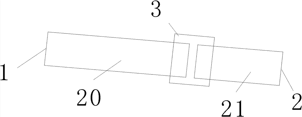
[0029] figure 2 It is a structural schematic diagram of the first embodiment of the segmented rotary kiln of the present invention, as figure 2 As shown, the segmented rotary kiln is composed of two cylinders including a first cylinder 20 and a second cylinder 21, and the first cylinder 20 and the second cylinder 21 are detachably connected to each other. . Wherein, the pit tail 1 of the entire rotary kiln is located in the first cylinder 20 , and the pit head 2 of the rotary kiln is located in the second cylinder ...


PUM


Abstract

The invention discloses a sectioned type rotary pit, which is characterized in that the sectioned type rotary pit is formed by a plurality of sections of cylinder bodies; and the adjacently-arranged cylinder bodies are mutually and detachably connected together. With the adoption of the scheme, all sections of the rotary pit can be separated cleaned according to different conditions; the sectioned type rotary pit is flexible and can be used for pointedly cleaning a formed ring generated in the rotary pit; and the production efficiency is improved.

Description

technical field [0001] The invention relates to the technical field of metallurgy, in particular to a segmented rotary kiln. Background technique [0002] At present, as a kind of rotary cylinder equipment, the rotary kiln has been widely used in metallurgy and other fields. The rotary kiln is installed at a slant. The materials in the rotary kiln first enter from the higher kiln tail. When the rotary kiln is working, the materials move toward the lower kiln head while rolling along the circumference. During the process, the burner installed at the kiln head of the rotary kiln heats the material, and generates the final reaction product through physical and chemical changes. [0003] The rotary kiln has the advantages of simple structure and relatively low cost. However, in the actual production of the rotary kiln, there is also the problem that it is easy to form a ring at the head of the kiln. Specifically, when the rotary kiln is working normally and the temperature in ...

Claims


Application Information

Patent Timeline
IPC IPC(8): F27B7/02
Inventor 谢洪恩文永才何群付卫国
Owner PANZHIHUA IRON AND STEEL
Learn More