Composite vacuum deposition method of combination magnetic field, lining special-shaped tube and porous baffle

A porous baffle and vacuum deposition technology, which is applied in vacuum evaporation plating, ion implantation plating, coating, etc., can solve the problems of film composition pollution, large particle defects, and low film deposition efficiency, so as to ensure uniformity, The effect of improving utilization efficiency

Pending Publication Date: 2019-07-09
魏永强
View PDF4 Cites 2 Cited by
  • Summary
  • Abstract
  • Description
  • Claims
  • Application Information

AI Technical Summary

Problems solved by technology

[0006] The purpose of the present invention is to solve the problem of low ionization rate and thin film deposition efficiency of traditional magnetron sputtering technology, the limitation of high melting point target material use, and the current high-power pulse magnetron sputtering. The plating method uses high melting point targets, low melting point pure metals (such as aluminum, tin) or multi-element alloy materials (such as AlSi alloys) and non-metallic materials (such as graphite and semiconductor materials Si) as targets that are prone to large particle defects, bending Low efficiency of arc plasma transmission caused by type magnetic filter technology, limitation of target element usage and uniform ablation, thin film deposition density and defects, deposition position limitation caused by vacuum chamber space and target source layout design, workpiece shape limitation and different target In order to solve problems such as contamination of film components caused by secondary sputtering of residues in multi-level magnetic field devices, pure metals with low melting points (such as aluminum, tin) or multi-element alloy materials (such as AlSi alloys) and non-metallic materials (such as graphite and Semiconductor material Si, etc.) as the target material of high-power pulsed magnetron sputtering, and then use the arc ion plating method to realize the high melting point refractory target material to produce continuous and stable plasma with high ionization rate, combined with multi-level magnetic field filtering method and The shape constraints of the lined bias conical tube, stepped tube and porous baffle combined device and the combined effect of bias electric field attraction can eliminate the large particle defects contained in the arc plasma, and at the same time ensure that the arc plasma has a higher The transmission efficiency is eliminated from the multi-level magnetic field through the combination of the lined bias conical tube, the stepped tube

Method used


Image

  • Composite vacuum deposition method of combination magnetic field, lining special-shaped tube and porous baffle
  • Composite vacuum deposition method of combination magnetic field, lining special-shaped tube and porous baffle
  • Composite vacuum deposition method of combination magnetic field, lining special-shaped tube and porous baffle

Examples


specific Embodiment approach 1

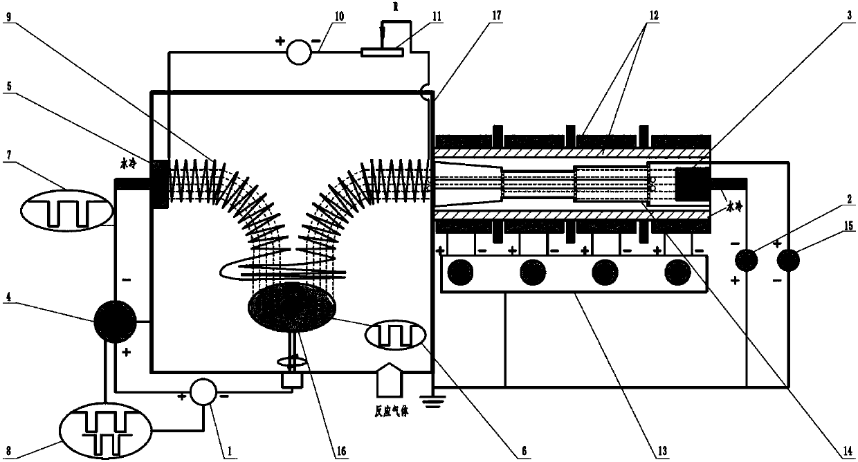
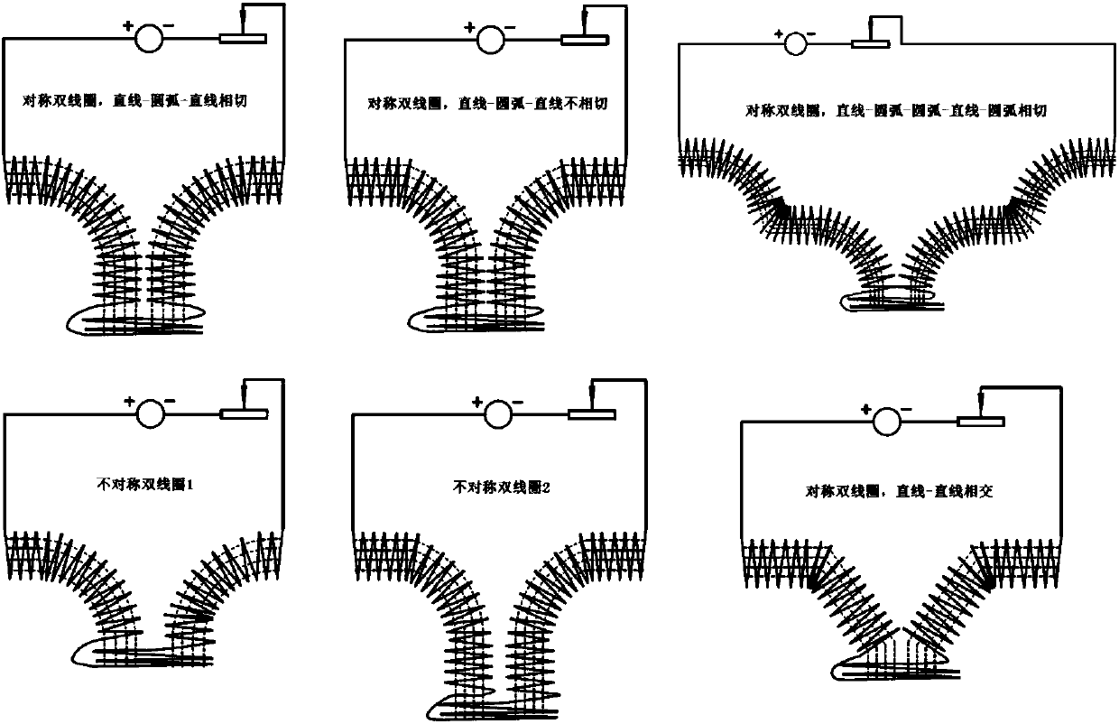
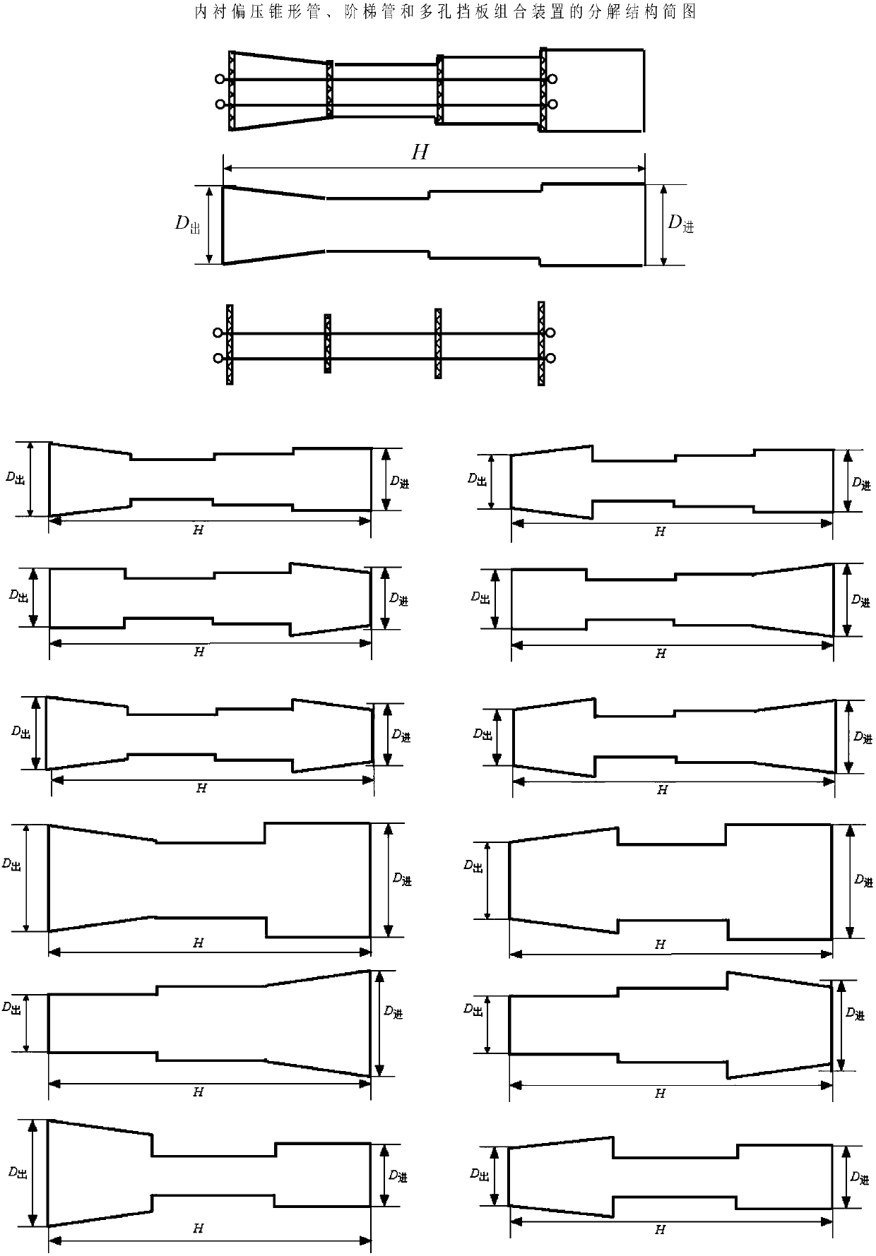
[0025] Specific embodiment one: the following combination Figure 1-4 This embodiment will be described. In this embodiment, a vacuum deposition method in which a combined magnetic field and a lined special-shaped tube and a porous baffle are combined includes a bias power supply (1), an arc power supply (2), and an arc ion plating target source (3). ), high-power pulsed magnetron sputtering power supply (4), high-power pulsed magnetron sputtering target source (5), bias power supply waveform oscilloscope (6), high-power pulsed magnetron sputtering power supply waveform oscilloscope (7), Waveform synchronization matching device (8), movable coil device (9), movable coil device power supply (10), varistor device (11), multi-stage magnetic field device (12), multi-stage magnetic field device power supply (13), lining bias a conical tube, a stepped tube and a porous baffle assembly (14), a lining bias power supply (15), a sample stage (16) and a vacuum chamber (17);

[0026] In ...

specific Embodiment approach 2

[0044] Specific embodiment 2: The difference between this embodiment and the first embodiment is that a combined magnetic field and a vacuum deposition method of lining a special-shaped tube and a porous baffle are connected, and the arc power supply (2) is turned on, and the multi-stage magnetic field power supply is turned on. (5) Adjust the multi-stage magnetic field device (12), turn on the lining bias power supply (15), adjust the bias voltage of the lining bias conical tube, the stepped tube and the porous baffle assembly (14), and turn on the power supply of the movable coil device (10) Adjust the movable coil device (9), adjust the output resistance of the varistor device (10), and control the bias power supply (1) and the high-power pulse magnetron sputtering power supply (4) by the waveform synchronization matching device (8) to be turned on at the same time. , the period of the output pulse of the high-power pulsed magnetron sputtering power supply (4) is an integer ...

specific Embodiment approach 3

[0045] Embodiment 3: The difference between this embodiment and Embodiment 1 is that a combined magnetic field and a vacuum deposition method of lining a special-shaped tube and a porous baffle are connected, the arc power source (2) is turned on, and the multi-stage magnetic field power source is turned on. (5) Adjust the multi-stage magnetic field device (12), turn on the lining bias power supply (15), adjust the bias voltage of the lining bias conical tube, the stepped tube and the porous baffle assembly (14), and turn on the power supply of the movable coil device (10) Adjust the movable coil device (9), adjust the output resistance of the varistor device (10), and control the bias power supply (1) and the high-power pulse magnetron sputtering power supply (4) by the waveform synchronization matching device (8) to be turned on at the same time. , the high-power pulsed magnetron sputtering power supply (4) outputs high-power pulses and the phase of the bias pulse waveform ou...


PUM


Abstract

The invention discloses a composite vacuum deposition method of a combination magnetic field, a lining special-shaped tube and a porous baffle, and belongs to the technical field of material surface treatment. The problems of contamination of thin films and target material usage restrictions by large particles, loss of magnetically filtered arc plasma, and instability of high power pulsed magnetron sputtering discharge in arc ion plating are solved. A device comprises a target source of arc ion plating, a multistage magnetic field device, a lining bias voltage special-shaped tube and porous baffle combination device, a movable coil device, a high power pulsed magnetron sputtering target source and relevant power supply, a waveform matching device, a bias voltage power supply, and the like;and thin film deposition is conducted, specifically, the device is connected, a system is started, working gas is injected when the vacuum degree in a vacuum chamber is less than 10<-4>Pa, a platingpower supply is turned on, the bias voltage power supply regulates energy of the plasma, the combination magnetic field and the lining special-shaped tube and porous baffle device eliminate large particle defects and guide transmission of the composite plasma, the loss in the vacuum chamber is reduced, and preparation technological parameters are set.

Description

technical field [0001] The invention relates to a vacuum deposition method combining a magnetic field, a lined special-shaped tube and a porous baffle, and belongs to the technical field of material surface treatment. Background technique [0002] In the process of preparing thin films by arc ion plating, the current density of arc spot is as high as 2.5~5×10 10 A / m 2 , causing molten liquid metal to appear at the arc spot position on the surface of the target, sputtering out in the form of droplets under the action of local plasma pressure, attached to the surface of the film or embedded in the film to form "macroparticles" (Macroparticles) Defects (BoxmanR L, Goldsmith S. Macroparticle contamination in cathodic arc coatings: generation, transport and control [J]. Surf Coat Tech, 1992, 52(1): 39-50.). In arc plasma, since the moving speed of electrons is much greater than that of ions, the number of electrons reaching the surface of large particles per unit time is greate...

Claims


Application Information

Patent Timeline
IPC IPC(8): C23C14/32C23C14/35C23C14/54
CPCC23C14/325C23C14/3485C23C14/352C23C14/54
Inventor 魏永强王好平宗晓亚张新国刘学申蒋志强
Owner 魏永强
Why Eureka
Try Eureka