Combined magnetic field and lining biased straight pipe composite filtering arc ion plating

A technology of arc ion plating and arc plasma, which is applied in the field of material surface treatment, can solve the problems of target material uniform ablation, pollution, large particle defects, etc., and achieve the effects of effective control, uniformity, and improvement of utilization efficiency

Pending Publication Date: 2019-07-09
魏永强
View PDF4 Cites 0 Cited by
  • Summary
  • Abstract
  • Description
  • Claims
  • Application Information

AI Technical Summary

Problems solved by technology

[0004] The purpose of the present invention is to solve the problem that the traditional arc ion plating method adopts high melting point target material, low melting point pure metal or multi-element alloy material and non-metallic material (such as graphite) as the target material, which is easy to produce large particle defects, and the curved magnetic filter technology causes arc. Low plasma transmission efficiency, limited use of target elements, uniform target ablation, film deposition density and defects, vacuum chamber space and deposition position limitations, workpiece shape limitations, and residues of different targets in multi-level magnetic field devices Combining the multi-stage magnetic field filtering method and the constraints of the shape of the lined bias straight tube device and the composite effect of bias electric field attraction to eliminate the large particle defects contained in the arc plasma, At the same time, ensure that the arc plasma passes through the lined bias straight pipe device and the multi-stage magnetic field filter device with high transmission efficiency, and then use the movable coil device to control the arc plasma transmitted from the multi-stage magnetic field device and the lined bias straight pipe de

Method used


Image

  • Combined magnetic field and lining biased straight pipe composite filtering arc ion plating
  • Combined magnetic field and lining biased straight pipe composite filtering arc ion plating
  • Combined magnetic field and lining biased straight pipe composite filtering arc ion plating

Examples


specific Embodiment approach 1

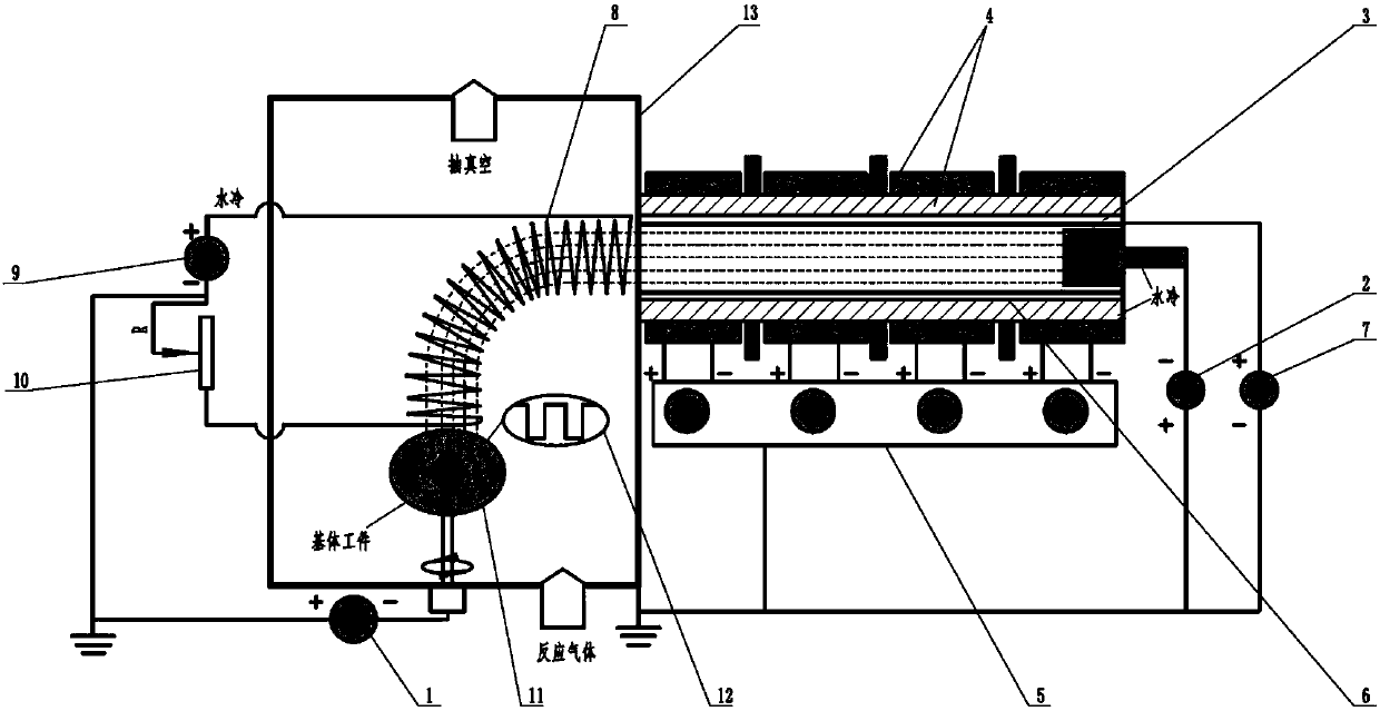
[0020] Specific implementation mode one: the following combination Figure 1-3 Describe this embodiment, the arc ion plating device used in this embodiment combined magnetic field and lined bias straight tube composite filter includes bias power supply (1), arc power supply (2), arc ion plating target source (3), Multi-stage magnetic field device (4), multi-stage magnetic field power supply (5), lined bias straight pipe device (6), lined bias power supply (7), movable coil device (8), movable coil device power supply (9) , a rheostat device (10), a sample stage (11), a bias power supply waveform oscilloscope (12) and a vacuum chamber (13);

[0021] In this device:

[0022] The substrate workpiece to be processed is placed on the sample stage (11) in the vacuum chamber (13), the multi-stage magnetic field device (4), the liner bias straight tube device (6), the movable coil device (8) and the vacuum chamber (13 ) are insulated from each other, the workpiece is placed on the s...

specific Embodiment approach 2

[0036] Embodiment 2: The difference between this embodiment and Embodiment 1 is that the device can also realize other functions: it can combine traditional DC magnetron sputtering, pulse magnetron sputtering, traditional arc ion plating and pulse cathode arc Combination of one or more than two methods, and then apply DC bias, pulse bias, DC pulse composite bias or bipolar pulse bias device on the workpiece for thin film deposition to prepare pure metal thin films and compounds with different element ratios Ceramic films, functional films and high-quality films with nano-multilayer or gradient structures.

specific Embodiment approach 3

[0037] Specific embodiment three: the difference between this embodiment and embodiment two is that the combined magnetic field is connected to the arc ion plating of the liner bias straight tube compound type filter, the arc power supply (2) is turned on, and the multi-stage magnetic field power supply (5 ) Adjust the multi-stage magnetic field device (4), turn on the lining bias power supply (7), the lining bias straight pipe device (6) maintains a DC positive bias, turn on the bias power supply (1), and turn on the power supply of the movable coil device ( 9) Adjust the movable coil device (8), adjust the output resistance of the rheostat device (10), adjust the process parameters, perform film deposition, and prepare multi-layer structure films with different stress states, microstructures and element ratios, and others are the same as in Embodiment 2 same.


PUM


Abstract

The invention discloses combined magnetic field and lining biased straight pipe composite filtering arc ion plating, and belongs to the technical field of material surface treatment. The combined magnetic field and lining biased straight pipe composite filtering arc ion plating solves the problem of contamination to thin films by macroparticles in a multi-stage magnetic field filtering device andloss of plasma during transfer. A device of the combined magnetic field and lining biased straight pipe composite filtering arc ion plating comprises a grid bias power supply, an arc ion plating target source and power supply, a multi-stage magnetic field device and power supply, a lining biased straight pipe device and grid bias power supply, a movable coil device and power supply, a sample stage, a bias power waveform oscilloscope and a vacuum chamber. Thin film deposition comprises the steps that the devices are connected, a system is started, when the vacuum degree in the vacuum chamber isless than 10<-4> Pa, working gas is introduced in, a film coating power supply is turned on, energy of the arc plasma is adjusted by the grid bias power supply, macroparticle defects in the arc plasma are eliminated and the transfer efficiency in the filtering device is improved through the lining biased straight pipe device and the multi-stage magnetic field device, the loss in the vacuum chamber is reduced, process parameters are set, and thin film preparation is performed.

Description

technical field [0001] The invention relates to an arc ion plating combined with a magnetic field and a liner bias straight tube compound filter, and belongs to the technical field of material surface treatment. Background technique [0002] In the process of preparing thin films by arc ion plating, due to the arc spot current density as high as 2.5~5×10 10 A / m 2 , causing molten liquid metal to appear at the arc spot position on the target surface, which is splashed out in the form of droplets under the action of local plasma pressure, and adheres to the surface of the film or is embedded in the film to form "macroparticles" (Macroparticles) Defects (BoxmanR L, Goldsmith S. Macroparticle contamination in cathodic arc coatings: generation, transport and control [J]. Surf Coat Tech, 1992, 52(1): 39-50.). In the arc plasma, since the movement speed of electrons is much greater than that of ions, the number of electrons reaching the surface of large particles per unit time is...

Claims


Application Information

Patent Timeline
IPC IPC(8): C23C14/32C23C14/56
CPCC23C14/325C23C14/564
Inventor 魏永强王好平刘源张华阳侯军兴蒋志强
Owner 魏永强
Why Eureka
Try Eureka