LED (Light-emitting Diode) backlight drive circuit, backlight module and liquid crystal display device

A technology of backlight drive circuit and power module, which is applied in the direction of electrical components, static indicators, instruments, etc., can solve the problem of high cost, and achieve the effect of convenient operation, improved reliability and high reliability

Active Publication Date: 2013-03-06
SHENZHEN CHINA STAR OPTOELECTRONICS TECH CO LTD
View PDF10 Cites 23 Cited by
  • Summary
  • Abstract
  • Description
  • Claims
  • Application Information

AI Technical Summary

Problems solved by technology

The light bar and the power module are generally connected with ordinary wires. The advantage is that it is

Method used


Image

  • LED (Light-emitting Diode) backlight drive circuit, backlight module and liquid crystal display device
  • LED (Light-emitting Diode) backlight drive circuit, backlight module and liquid crystal display device

Examples


Embodiment Construction

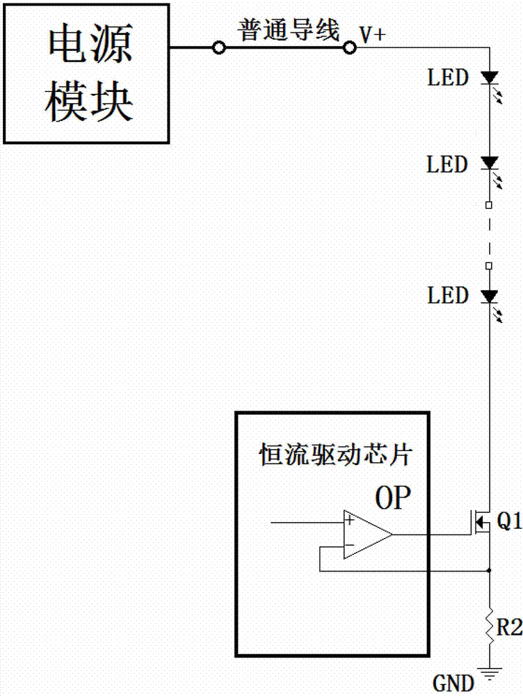
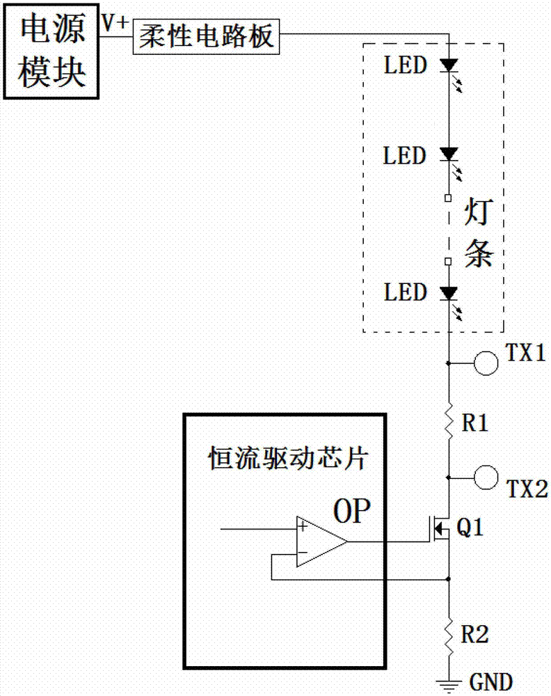
[0018] The invention discloses a liquid crystal display device. The liquid crystal display device includes a backlight module. The backlight module includes an LED backlight drive circuit. The LED backlight drive circuit includes a light bar and a measuring resistor connected in series with the light bar. The two ends of the measurement resistor are respectively provided with test points, and the area of ​​the test points is larger than the area of ​​the resistance pad.

[0019] Because the present invention adds test points at both ends of the measurement resistance, the area of ​​the test points is larger than that at both ends of the test resistance, so that the probes of measuring tools such as multimeters can be in reliable contact with the test points, and it is not easy to touch other components. Measurement reliability. The inventor further found through research that because the pads of the test resistors are relatively small, when the wires are soldered, the solder j...


PUM


Abstract

The invention discloses an LED (Light-emitting Diode) backlight drive circuit, a backlight module and a liquid crystal display device. The LED backlight drive circuit comprises a light bar, and a power supply module coupled with the light bar, wherein the light bar is connected with the power supply module through a flexible circuit board; the light bar is also serially connected with a measuring resistance; and test points are respectively arranged on two ends of the measuring resistance. According to the LED backlight drive circuit, the test points are added on the two ends of the measuring resistance, so that a probe of a measuring tool such as a universal meter can be reliably contacted with the test points but can not be easy to contacted with other components, and the reliability of measurement is improved. When an oscilloscope is used for measuring, fine wire conductors can be directly welded on the test points, the test points keep away from a bonding pad of the measuring resistance, short circuit is not easy to occur between wire conductors, the operation is convenient, and the reliability is high.

Description

technical field [0001] The invention relates to the field of liquid crystal display, and more specifically relates to an LED backlight driving circuit, a backlight module and a liquid crystal display device. Background technique [0002] With the popularization of LEDs, LEDs have been widely used as backlight sources in existing liquid crystal display devices. see figure 1 The specific method is to connect multiple LEDs in series to form a light bar, and then connect both ends of the light bar to the power module, which is driven by the power module. The light bar and the power module are generally connected with ordinary wires. The advantage is that it is easier to measure the current of the LED string, but the cost of connecting with ordinary wires is higher. Contents of the invention [0003] The technical problem to be solved by the present invention is to provide an LED backlight drive circuit, a backlight module and a liquid crystal display device that can measure ...

Claims


Application Information

Patent Timeline
IPC IPC(8): G09G3/34G09G3/36
CPCG09G3/34G09G3/36H05B45/10H05B45/395Y02B20/30
Inventor 张华
Owner SHENZHEN CHINA STAR OPTOELECTRONICS TECH CO LTD
Why Eureka
Try Eureka