Gear pump

A technology of gear pumps and gears, applied to pumps, pump components, rotary piston pumps, etc., can solve problems such as increased manufacturing costs, and achieve the effects of small volume flow and reduced loss

Active Publication Date: 2013-03-06
OERLIKON TEXTILE GMBH & CO KG
View PDF14 Cites 6 Cited by
  • Summary
  • Abstract
  • Description
  • Claims
  • Application Information

AI Technical Summary

Problems solved by technology

However, this system requires construction of return threads in the circumference of the pump shaft, which leads to increased manufacturing costs

Method used


Image

  • Gear pump
  • Gear pump
  • Gear pump

Examples


Embodiment Construction

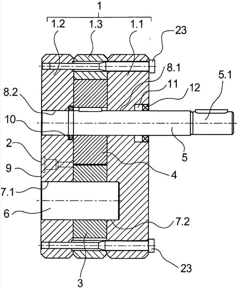
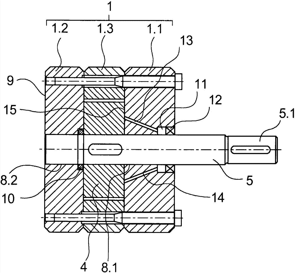
[0023] exist figure 1 with 2 A first embodiment of a gear pump according to the invention is shown in . here, figure 1 schematically shows a cross-sectional view of a gear pump and figure 2 A sectional view of the gear pump is shown in a section offset by 90° from the cross-sectional view.

[0024] The gear pump comprises a pump housing 1 . The pump housing 1 is constructed in multiple parts and has a plurality of housing plates 1 . The intermediate housing plate 1.3 has a recess for the two gear wheels 3 and 4 which mesh with each other. The middle housing plate 1.3 is held together with the gears 3 and 4 between the outer housing plates 1.1 and 1.2. One of the gears 3 is rotatably provided on the support pin 6 . For this purpose, the bearing pin 6 is held in a pin hole 7 . 1 in the outer housing plate 1 . 2 and in a pin hole 7 . 2 configured as a blind hole in the opposite outer housing plate 1 . 1 . The second gearwheel 4 is arranged on the pump shaft 5 in a rotati...


PUM


Abstract

A gear pump is described with a plurality of gear wheels which intermesh in order to deliver a pumping medium, are held rotatably in a pump case and deliver a pumping medium from a priming zone into a delivery pressure zone of the pump case. One of the gear wheels is driven by a pump shaft which protrudes with a coupling end out of the pump case. In order to seal the pump case, a shaft sealing ring is held around the circumference of the pump shaft, wherein, in order to avoid material deposits, the shaft sealing ring is assigned, according to the invention, an interior flushing chamber on the circumference of the pump shaft, the flushing chamber being connected to the delivery pressure zone of the pump case by a feed channel in the pump case.

Description

technical field [0001] The invention relates to a gear pump according to the preamble of claim 1 . Background technique [0002] For conveying and metering fluids, it is known to use gear pumps having a plurality of gears meshing with one another, which convey the fluid between a suction zone and a pressure zone. For this purpose, at least one gear wheel is driven by a pump shaft which is connected to a drive arranged outside the pump housing. Such a pump shaft is mounted in a pump housing and sealed against the environment by a shaft sealing ring. The shaft sealing ring prevents the escape of the conveyed fluid, which flows through the bearing point of the pump shaft through leakage and deposits in the area immediately in front of the shaft sealing ring. [0003] In order to be able to replace such a leakage flow on a regular basis, for example EP 0 669 465 A1 discloses a gear pump in which the leakage flow flowing through the bearing point of the pump shaft enters an ann...

Claims


Application Information

Patent Timeline
Patent Type & Authority Applications(China)
IPC IPC(8): F04C2/14
CPCF04C13/001F04C13/005F04C15/0038F04C2/086F04C2/14
Inventor D·维茨勒
Owner OERLIKON TEXTILE GMBH & CO KG
Why Eureka
Try Eureka