Gas-liquid separator combining centrifugal separation, baffle plate and filter

A gas-liquid separator and centrifugal separation technology, applied in the field of separators, can solve the problems of bulky equipment, low separation capacity, and large footprint, and achieve the effect of compact structure and high-efficiency separation

Inactive Publication Date: 2013-03-13
邢学军
5 Cites 24 Cited by

AI-Extracted Technical Summary

Problems solved by technology

A common horizontal structure gas-liquid separator, the main structure is that the shell is equipped with baffles, pre-separation components and filters, etc. The disadvantage of this separator is that the separation capacity is low, the equipment is heavy, and it occupies a large area
Another common structural form is the centrifugal separator, which utilizes the difference in gas-liquid density, and through the high-speed rotation of the gas-liquid mixture, the liquid droplets are gathered on the wall of the separator. The disadvantage of this equipment is tha...

Abstract

The invention discloses a gas-liquid separator combining centrifugal separation, a baffle plate and a filter. A top cover is arranged at the upper end of a vertical cylindrical shell, an inversely conical centrifugal separation liquid separation cavity is arranged at the lower end of the vertical cylindrical shell, a feeding opening is arranged at the upper middle part, and a spiral type pre-separator is arranged at the inner side of the vertical cylindrical shell; a gas guide pipe is arranged at the upper end of the top cover; a gas puffier is arranged at the center position of the inner lateral face of the top cover; a liquid outlet is arranged at the lower end of the inversely conical centrifugal separation liquid separation cavity; the feeding opening is connected with the spiral type pre-separator; the spiral type pre-separator comprises a sealed type spiral stream guidance sheet, an open type spiral stream guidance sheet and a spiral absorption property filter; and the gas purifier comprises an absorption filter, a NO.1 inversely conical bottom-open baffle plate, a conical top-open baffle plate, a NO.2 inversely conical bottom opening baffle plate, a baffle plate connection rod and a porous medium spoiler. The gas-liquid separator is compact in structure; various separation principles including centrifugal separation, impact, condensation capturing, absorption filtering and inertia separation are integrated inside the separator; and the gas-liquid efficient separation can be satisfied.

Application Domain

Technology Topic

EngineeringPorous medium +5

Image

  • Gas-liquid separator combining centrifugal separation, baffle plate and filter
  • Gas-liquid separator combining centrifugal separation, baffle plate and filter
  • Gas-liquid separator combining centrifugal separation, baffle plate and filter

Examples

  • Experimental program(1)

Example Embodiment

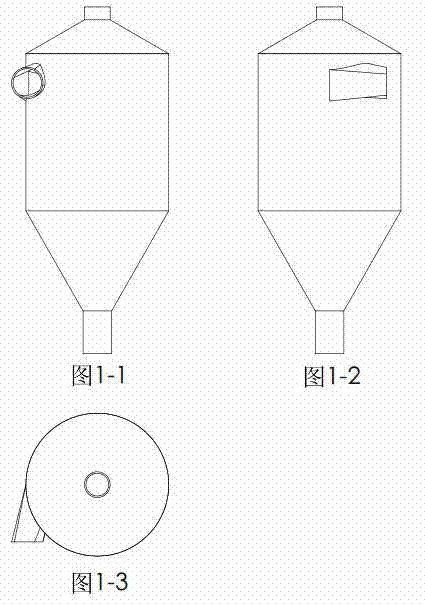
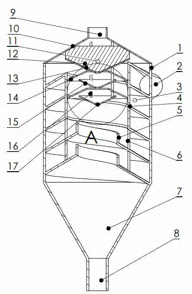
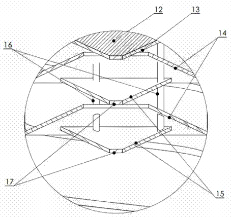
[0021] As shown in the figure, the gas-liquid separator with a combination of centrifugal separation, baffle and filter includes a vertically placed cylindrical separator shell 1, a feed port 2, a spiral pre-separator 3, and a closed spiral guide Flow sheet 4, open spiral guide vane 5, spiral adsorptive filter 6, inverted cone centrifugal separation liquid collection chamber 7, liquid outlet 8, air guide tube 9, top cover 10, gas purifier 11, adsorptive filtration 器12, No. 1 inverted cone bottom opening baffle 13, cone top opening baffle 14, No. 2 inverted cone bottom opening baffle 15, baffle connecting rod 16 and porous medium baffle 17;
[0022] The top of the cylindrical separator shell 1 is provided with a top cover 10, the middle and upper part is provided with a feed port 2, and the inner side is provided with a spiral pre-separator 3. The spiral pre-separator 3 is connected with the feed port 2, and the cylindrical separation The lower end of the device housing 1 is provided with an inverted cone centrifugal separation liquid collection chamber 7;
[0023] A gas purifier 11 is provided at the center of the inner side of the top cover, and an air duct 9 is provided at the upper end;
[0024] A liquid outlet 8 is provided at the lower end of the inverted cone centrifugal separation liquid collection chamber 7;
[0025] The spiral pre-separator 3 includes a closed spiral guide vane 4, an open spiral guide vane 5, and a spiral adsorbent filter 6. The entrance of the spiral pre-separator 3 is connected with the feed inlet 2, and the top is closed Spiral guide vane 4, the bottom is provided with an open spiral guide vane 5, the open spiral guide vane 5 is installed with a spiral adsorbent filter 6, the outlet of the spiral pre-separator 3 and the inverted cone centrifugal separation set The liquid cavity 7 intersects tangentially;
[0026] The gas purifier 11 includes an adsorbent filter 12, a No. 1 inverted cone bottom opening baffle 13, a cone top opening baffle 14, a No. 2 inverted cone bottom opening baffle 15, and a baffle connecting rod 16. And the porous medium baffle plate 17, the baffle plate of the gas purifier 11 is connected by the baffle plate connecting rod 16 and fixed at the center of the inner side of the top cover. The top of the gas purifier 11 is an adsorbent filter 12, which is an adsorbent filter. The lower end of 12 is provided with a No. 1 inverted cone bottom opening baffle 13, and the No. 1 inverted cone bottom opening baffle 13 is alternately provided with a cone top opening baffle 14 and a No. 2 inverted cone bottom opening baffle 15 , The bottom opening of the No. 2 inverted cone bottom opening baffle plate 15 is provided with a porous medium baffle plate 17.
[0027] The flow cross-section of the closed spiral guide vane 4 of the spiral pre-separator 3 is quadrangular with upper and lower slopes. The bottom surface of the open spiral guide vane 5 is a slope, and the inner edge is provided with steps. The spiral pre-separation The shell 1 can be set as the outer wall surface of the spiral pre-separator 3 (the closed spiral guide vane 4 and the open spiral guide vane 5 are welded to the inside of the housing 1), or the spiral pre-separator can be installed The outer casing of the device 3 is fixed inside the casing 1.
[0028] The diameter of the upper end surface of the No. 1 inverted cone bottom opening baffle 13 of the gas purifier 11 is larger than the upper end surface diameter of the No. 2 inverted cone bottom opening baffle plate 15, and the cone top opening baffle plate of the gas purifier 11 The diameter of the lower end surface of 14 is slightly smaller than the inner diameter of the spiral pre-separator 3. The tapered top opening baffle 14 and the second inverted cone bottom opening baffle 15 of the gas purifier 11 are multiple pieces, which are installed in a staggered manner.
[0029] The working process of the present invention is as follows:
[0030] In the normal working process, the mixture composed of gas and liquid is sent to the feed port 2 through the external pipeline. The mixture enters the spiral pre-separator 3 and begins to make centrifugal movement around the closed spiral guide vane 4. Under the action, the dense liquid is thrown to the outer side wall of the spiral pre-separator 3, most of the gas is separated and flows against the inner side wall, and then flows into the open spiral guide vane 5, and the liquid continues downward under the action of centrifugal force and gravity Do a rotating flow, the remaining gas in the liquid will continue to be separated under the action of centrifugal force. The separated gas enters the separator cavity through the spiral adsorption filter 6, and the airflow is filtered out when it passes through the spiral adsorption filter 6. Most of the droplets in the airflow, the droplets agglomerate on the inner surface of the spiral adsorbent filter 6 and become larger. When reaching a certain level, the droplets flow out of the spiral adsorbent filter 6 under the impact of the airflow and gravity, and collect to Near the inner edge of the open spiral guide vane 5, it merges with the rotating liquid along the guide vane. When the liquid flows to the inverted cone centrifugal separation liquid collection chamber 7, the liquid carries a small amount of gas and performs tangential rotation centrifugal movement. The liquid continues to rotate in the inverted cone centrifugal separation liquid collection chamber 7 to reach the liquid outlet 8 and separate the remaining gas in the liquid.
[0031] The gas enters the separator chamber, and the gas carries a small part of the liquid droplets, and moves upward and hits the No. 2 inverted cone bottom opening baffle plate 15. Due to the large momentum of the gas flow droplets, it is not easy to change the flow direction, and the liquid droplets are captured on the baffle plate Above, the droplets condensate and become larger and flow to the inverted cone centrifugal separation sump 7 under the action of gravity. After several changes of direction, a large number of droplets in the airflow are captured, and finally the airflow is guided by the adsorbent filter 12 The air pipe 9 is discharged, and when the air flows through the absorbent filter flow 12, the liquid particles coalesce and grow on the inner surface of the filter element due to the coalescence function of the filter medium; when the droplets reach a certain size, they flow out of the filter due to the impact of gravity and air flow. Flow through the bottom openings of the No. 1 inverted cone bottom opening baffle 13 and the No. 2 inverted cone bottom opening baffle 15 to the inverted cone centrifugal separation liquid collection chamber 7, and the No. 2 inverted cone bottom opening baffle 15 The porous medium baffle plate 17 in the bottom opening has two functions. One is to prevent the air flow from short-circuiting the baffle plate to directly move upward, and the other is that the captured droplets can flow to the inverted cone through the porous medium baffle plate 17 under the action of gravity. Shape centrifugal separation liquid collection chamber 7.
[0032] It should be noted here that the number of the cone-shaped top opening baffle 14 and the second inverted cone bottom opening baffle 15 of the present invention, and the number of cycles of the closed spiral guide vane 4 and the open spiral guide vane 5 It can be determined according to needs, which should be known to those skilled in the art, and will not be repeated here.

PUM

no PUM

Description & Claims & Application Information

We can also present the details of the Description, Claims and Application information to help users get a comprehensive understanding of the technical details of the patent, such as background art, summary of invention, brief description of drawings, description of embodiments, and other original content. On the other hand, users can also determine the specific scope of protection of the technology through the list of claims; as well as understand the changes in the life cycle of the technology with the presentation of the patent timeline. Login to view more.

Similar technology patents

Municipal solid waste comprehensive treatment and recycling device

InactiveCN102039303AReduce the spread of odorsCompact structureSievingScreeningWater pipeMetal recycling
Owner:HENAN AOSI ENVIRONMENTAL PROTECTION MACHINE

Classification and recommendation of technical efficacy words

  • Compact structure
  • Efficient separation

Methods for concentrating microalgae

InactiveUS20090162919A1Efficient ConcentrationEfficient separationUnicellular algaeMicroorganism separationNannochloropsisBiology
Owner:AURORA ALGAE

Preparation method of reed or straw cellulose pulp

InactiveCN101736646AEfficient separationImprove protectionNon-woody plant/crop pulpFinely-divided material pretreatmentChemistryFiber
Owner:INST OF CHEM CHINESE ACAD OF SCI

Method for separating iron, vanadium and titanium from schreyerite

ActiveCN103526051AEfficient separationAvoid high temperature reduction and meltingMagnetic separationAdhesiveMetal
Owner:PANZHIHUA IRON & STEEL RES INST OF PANGANG GROUP
Why Eureka
Try Eureka