Bottom die and die set link mechanism of bottle blowing machine

A technology of linkage linkage and rod mechanism, which is applied to other household appliances, household appliances, applications, etc., can solve the problems of bulky equipment, affect the working environment, and high cost investment, and achieve simple equipment structure, improve matching accuracy, and improve operating efficiency Effect

Active Publication Date: 2013-03-13
GUANGZHOU TECH LONG PACKAGING MACHINERY CO LTD
View PDF6 Cites 15 Cited by
  • Summary
  • Abstract
  • Description
  • Claims
  • Application Information

AI Technical Summary

Problems solved by technology

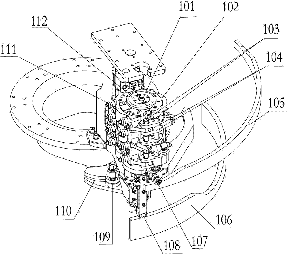
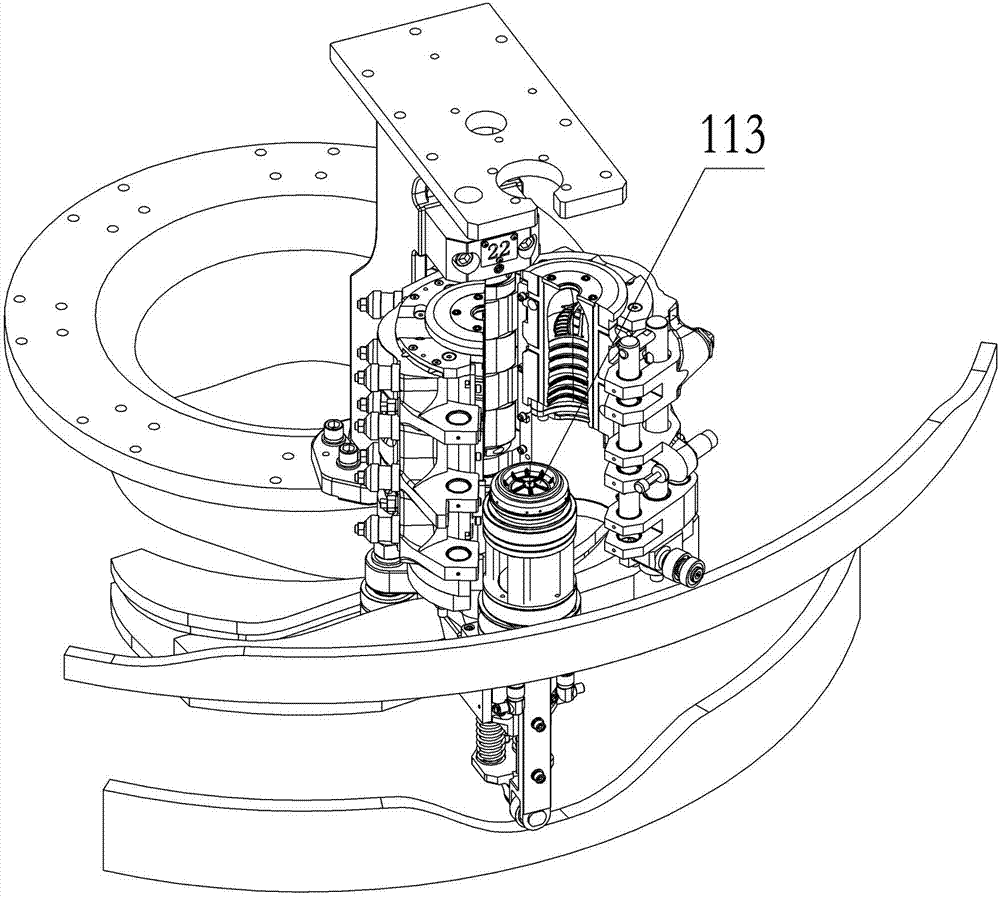
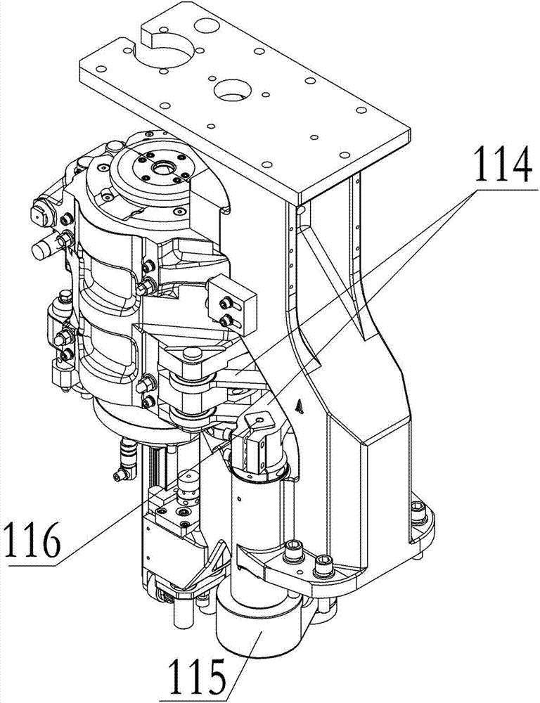
The problems existing in the prior art are as follows: 1. With the gradual increase of the operating speed of the equipment, the precision of cooperation between the lifting of the bottom mold, the opening and closing of the mold base and the lifting of the clamping pin is relatively high, so that the lifting guide rail of the bottom mold 1. The higher the accuracy requirements of the mold base opening and closing guide rails and the mold locking guide rails; 2. With the gradual increase of the operating speed of the equipment, when the rollers run to the corners of the bottom mold lifting guide rail surface, the impact sound caused by the instantaneous contact with the corners becomes more and more large, and the noise will b

Method used


Image

  • Bottom die and die set link mechanism of bottle blowing machine
  • Bottom die and die set link mechanism of bottle blowing machine
  • Bottom die and die set link mechanism of bottle blowing machine

Examples


Embodiment 1

[0014] Embodiment one, such as Figure 4 to Figure 7 As shown, there is a bottom mold lifting roller 8 on the bottom mold lifting connecting rod 2; the slideway 4 with a height difference curve is located on the surface of the bottom mold lifting guide plate 3; the device for controlling the movement of the opening and closing mold connecting rod 1 is the opening and closing mold roller 7. The lifting device that drives the bottom mold is that the bottom mold lifting guide plate 3 is connected to the bottom mold lifting slide rail 5, and the bottom mold lifting bracket 6 is connected with the bottom mold lifting slide rail 5, so that the bottom mold lifting slide rail 5 drives the bottom mold Lifting bracket 6 lifts, and then drives bottom mold lifting; Bottom mold lifting slide rail 5 slides in slide rail seat 9, and slide rail seat 9 is arranged on the formwork support 10.

[0015] When the equipment is running, the mold opening and closing roller 7 on the opening and closin...

Embodiment 2

[0017] In the second embodiment, the structure and movement mode of the bottle blowing machine are similar to those in the first embodiment, the difference is that the lower edge of the lifting guide plate 3 of the bottom mold forms a slideway with a height difference curve. Bottom mold lifting roller 8 extends to the lower edge slideway of bottom mold lifting guide plate 3, and under the swing of opening and closing mold connecting rod 1, it drives bottom mold lifting connecting rod 2 to move on the lower edge of bottom mold lifting guide plate 3. After arriving at the predetermined position, the bottom mold will drop to the original position under its own gravity after the bottle blowing is completed.

Embodiment 3

[0018] Embodiment 3, the structure and movement mode of the bottle blowing machine are similar to Embodiment 1, the difference is that the driving device for controlling the swing of the mold opening and closing rod 1 is a stepping motor. A stepping motor is installed on the opening and closing mold connecting rod 1, and the stepping motor drives the opening and closing mold connecting rod 1 to swing, thereby realizing the linkage of the opening and closing of the mold frame and the lifting of the bottom mold.


PUM


Abstract

The invention discloses a bottom die and die set link mechanism of a bottle blowing machine, which ensures that the opening and the closing of a die set and the ascending and the descending of a bottom die are integrated, namely the bottom die descends or ascends when the die set is opened or closed. The link mechanism has the effects of improving the matching precision between the bottom die and the die set in the working process, also simplifying equipment, saving the used space, reducing the cost, effectively reducing the noise intensity, prolonging the service life of a roller and avoiding huge impact caused by the fact that the roller is in instant contact with a corner of a lifting guide rail of the bottom die when the equipment rotates at a high speed.

Description

technical field [0001] The invention relates to a connecting rod mechanism, in particular to a linkage connecting rod mechanism between a bottom mold and a mold base of a bottle blowing machine. Background technique [0002] Blow molding machine is equipment in the field of processing and manufacturing plastic bottles such as beverage bottles, oil bottles, and medicine bottles. The blow molding machine includes left and right mold frames that can be opened and closed. The opening and closing device of the frame makes the opening and closing movement. After the left and right mold frames are closed, a cavity is formed inside, and there is another bottom mold that extends into or exits the cavity through the lifting device. The entire blowing process of the blow molding machine is compact and saves It saves time and effort, and the blow molding machine can automatically cycle, which improves the work efficiency. [0003] Such as figure 1 , figure 2 and image 3 As shown,...

Claims


Application Information

Patent Timeline
IPC IPC(8): B29C49/42B29C49/56B29L22/00
Inventor 吴志刚宁远鹏刘青山陈盛基
Owner GUANGZHOU TECH LONG PACKAGING MACHINERY CO LTD
Why Eureka
Try Eureka