Tank bottom vacuum sampling ball valve

A sampling ball and vacuum technology, applied in the valve details, valve device, valve shell structure and other directions, can solve the problems of poor valve plate sealing, difficult maintenance, easy air leakage of the shaft center, etc., to prevent scalding, and the valve body has a compact structure Effect

Active Publication Date: 2013-03-13
WUXI SMART AUTO CONTROL ENG CO LTD
View PDF4 Cites 1 Cited by
  • Summary
  • Abstract
  • Description
  • Claims
  • Application Information

AI Technical Summary

Problems solved by technology

However, when the gate valve is closed, the valve plate is not tightly sealed and the axis is prone to air leakage, so there is a certain risk in use, and the overall size is large, and maintenance is difficult; the flow resistance of the stop valve is large, and the force required for opening and closing is relatively large Not suitable for media with particles, high viscosity and easy to coke

Method used


Image

  • Tank bottom vacuum sampling ball valve
  • Tank bottom vacuum sampling ball valve

Examples


Embodiment Construction

[0015] The present invention will be further described below in conjunction with specific drawings and embodiments.

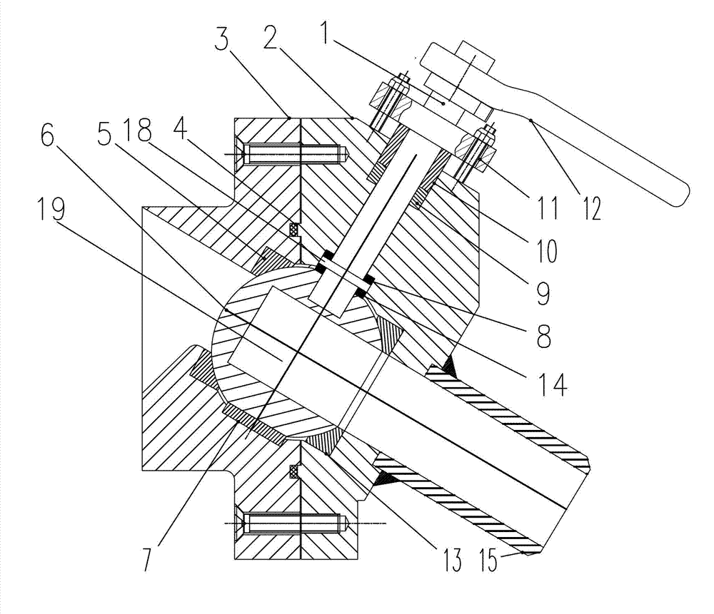
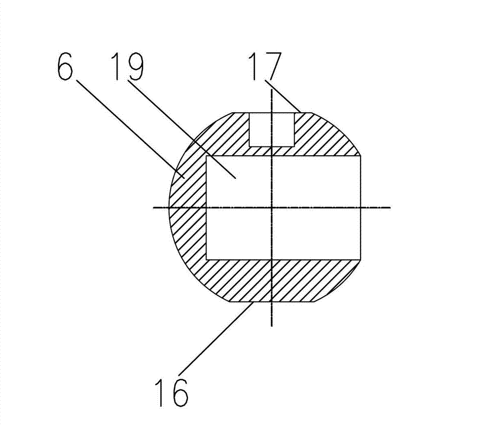
[0016] As shown in the figure: the tank bottom vacuum sampling ball valve includes an upper valve body 3, a lower valve body 2, an upper valve seat 5, a lower valve seat 13 and a valve ball 6, and the upper valve body 3 and the lower valve body 2 are fixedly connected. The upper valve body 3 is equipped with an upper valve seat 5, an upper ball valve bearing 7 and a stem thrust bearing 8, and a lower valve seat 13 and a lower ball valve bearing 14 are installed in the lower valve body 2, and the upper valve seat 5 and the lower valve seat A valve ball 6 is installed between 13, a sampling cavity 19 is opened in the valve ball 6, a first plane 16 and a second plane 17 are opened on the valve ball 6, and the valve ball 6 sits on the ball valve bearing through the first plane 16 7, the valve ball 6 sits on the lower ball valve bearing 14 through the second plane 1...


PUM


Abstract

The invention relates to a tank bottom vacuum sampling ball valve, which mainly comprises an upper valve body and a lower valve body which are fixedly connected. An upper valve seat is installed in the upper valve body. A valve ball is installed between the upper valve seat and the lower valve seat. A sampling chamber is arranged in the valve ball. A transmission shaft is rotatably and hermetically installed in the lower valve body. The internal end part of the transmission shaft is fixedly connected with the valve ball. A line which is connected with the circle center of a first plane and the circle center of a second plane is overlapped with the axis of the transmission shaft. A circular ring flange is arranged on the transmission shaft at the external end of the valve ball. One end surface of the circular ring flange is in contact with a lower ball valve bearing. The other end surface of the circular ring flange is in contact with a valve stem thrust bearing. The tank bottom vacuum sampling ball valve has the advantages that a handle can be enabled to be far away from the heat preserving layer of a vacuum container and accidents such as scalding can be prevented from occurring; the situation that the vacuum degree of the container is destroyed because the container is communicated with the atmosphere in a ball body switching process; and maximum sealing specific pressure of different materials can be realized by using minimum pretightening force.

Description

technical field [0001] The invention relates to a valve body suitable for various tank bottom vacuum sampling working conditions, in particular to a tank bottom vacuum sampling ball valve. Background technique [0002] Generally, valves with a nominal pressure lower than the standard atmospheric pressure are called vacuum valves. These valves are mainly used in vacuum negative pressure systems, condensation and high-pressure drainage systems, and are used as opening and closing isolation devices to ensure good isolation between the system and the atmosphere. At present, vacuum gate valves and vacuum globe valves are the most commonly used in the market. However, when the gate valve is closed, the valve plate is not tightly sealed and the axis is prone to air leakage, so there is a certain risk in use, and the overall size is large, and maintenance is difficult; the flow resistance of the stop valve is large, and the force required for opening and closing is relatively large ...

Claims


Application Information

Patent Timeline
Patent Type & Authority Applications(China)
IPC IPC(8): F16K5/06F16K5/08F16K41/02F16K27/06
Inventor 陈彦孙迟月史强修武显强
Owner WUXI SMART AUTO CONTROL ENG CO LTD
Why Eureka
Try Eureka