Lens driving device

A lens driving device and lens technology, which is applied in electromechanical devices, installation, optics, etc., can solve problems such as image blur and shaking, and achieve the effects of increasing yield, reducing occupied area, and not being prone to permanent deformation

Active Publication Date: 2015-07-22
JINLONG MACHINERY & ELECTRONICS CO LTD
View PDF13 Cites 0 Cited by
  • Summary
  • Abstract
  • Description
  • Claims
  • Application Information

AI Technical Summary

Problems solved by technology

In addition, when the lens support moves along the optical axis, it is easily shaken by the radial force, resulting in blurred images captured by the lens.

Method used


Image

  • Lens driving device
  • Lens driving device
  • Lens driving device

Examples


Embodiment 1

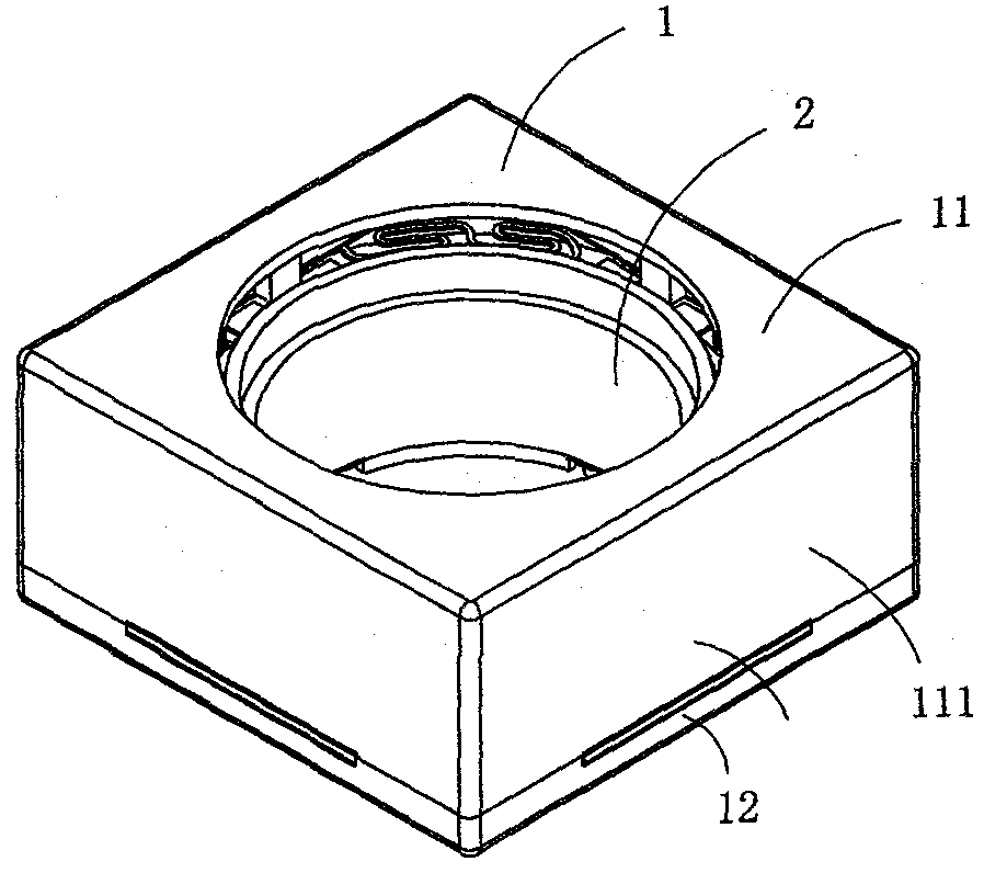
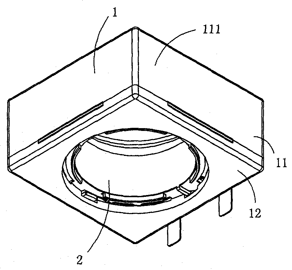
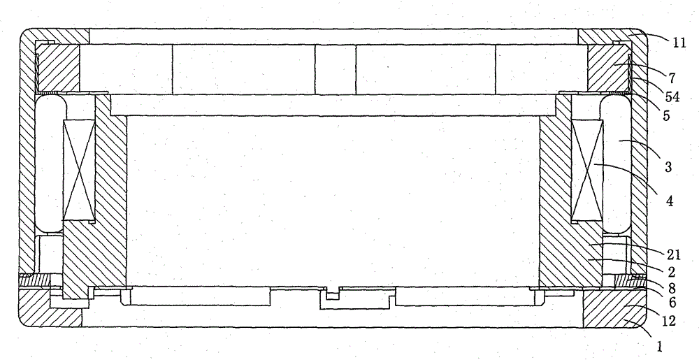
[0024] Figure 1 to Figure 5 A first embodiment of the invention is shown, in which figure 1 It is a schematic diagram of a three-dimensional structure of the first structure of the present invention; figure 2 for figure 1 A schematic diagram of the three-dimensional structure of the voice coil motor when viewed from another angle; image 3 for figure 1 A cross-sectional view of the voice coil motor shown; Figure 4 for figure 1 An exploded view of the voice coil motor shown; Figure 5 for figure 1 A schematic diagram of the three-dimensional structure of the upper shrapnel in the voice coil motor shown.

[0025] This embodiment is a lens driving device, see Figure 1 to Figure 5 , including a housing 1, and a lens carrier 2, a magnet assembly 3, a coil 4, an upper elastic piece 5, a lower elastic piece 6, an upper elastic piece bracket 7 and a lower insulating gasket 8 arranged in the housing 1; the lens carrier 2 is set Between the upper elastic piece 5 and the low...

Embodiment 2

[0036] Image 6 It is a schematic three-dimensional structure diagram of the upper elastic piece in the second structure of the present invention, showing a second specific embodiment of the present invention.

[0037]This embodiment is basically the same as Embodiment 1, except that: the upper elastic piece 5 is no longer provided with a connection area 55 for connecting two adjacent fixing areas 51, and a connecting area 55 for connecting two adjacent fixing areas 51 is provided between the fixing areas 51. A gap 511 separating two adjacent fixing regions 51 . In addition, the specific shape of the upper elastic piece 5 is also different from that of the first embodiment.

[0038] Above-mentioned embodiment 1 to embodiment 2 have the following advantages:

[0039] (1) The structure is relatively reasonable and compact, and the magnetic conducting ring in the traditional lens driving device is no longer needed, so as to avoid the disadvantage of lens carrier eccentricity ca...


PUM


Abstract

The invention discloses a lens driving device. The lens driving device comprises a casing, a lens carrier, a magnet assembly, a coil, an upper elastic piece and a lower elastic piece, wherein the lens carrier, the magnet assembly, the coil, the upper elastic piece and the lower elastic piece are arranged in the casing, the lens carrier is arranged between the upper elastic piece and the lower elastic piece, the magnet assembly is arranged on the periphery of the lens carrier, the coil is arranged between the magnet assembly and the lens carrier, the inner wall of the coil is adhered to and fixed on the outer wall of the lens carrier through glue, and a glue containing groove which is used for containing the redundant glue is arranged on the outer wall of the lens carrier. The lens driving device is reasonable and compact in structure, and magnetic conducting rings in traditional lens driving devices are not required, so that defects that lens carriers are eccentric due to the fact that magnetic forces of magnetic conducting rings are too strong can be avoided, the manufacturing process is simplified, and the manufacturing cost can be effectively reduced.

Description

technical field [0001] The invention relates to a lens driving device, in particular to a lens driving device applied to a camera, a video camera, or a mobile phone with a camera function to drive the lens to move to adjust the focal length. Background technique [0002] The driving device for adjusting the focal length of a traditional camera usually includes stepping motors, gears, cams and connecting rods. For example, Chinese patent document CN2938165Y discloses a lens structure with a stable autofocus function, including a housing, a motor, a first A gear, a second gear, a lens module and an elastic component, the motor is arranged in the casing, the first gear is arranged in the casing and fixed on the axis of the motor, the second gear is arranged in the casing In the body and vertically meshed with the first gear, the upper surface of the second gear has a spiral slope, the lens module is arranged in the housing, and the lens module has a spiral slope with the second...

Claims


Application Information

Patent Timeline
Patent Type & Authority Patents(China)
IPC IPC(8): G02B7/02G02B7/04H02K33/18G03B30/00
Inventor 金绍平方绍斌夏太红金士雷黄晓敏颜石磊
Owner JINLONG MACHINERY & ELECTRONICS CO LTD
Why Eureka
Try Eureka