A lens driving device
A lens driving device and lens technology, applied in electromechanical devices, installation, optics, etc., can solve problems such as shaking and image blurring, and achieve the effects of reducing the occupied area, improving the yield, and having a reasonable and compact structure
- Summary
- Abstract
- Description
- Claims
- Application Information
AI Technical Summary
Problems solved by technology
Method used
Image

Examples
Embodiment 1
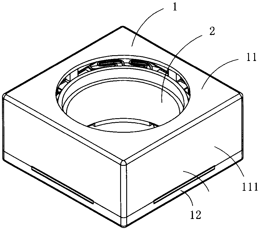
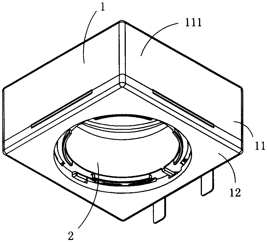
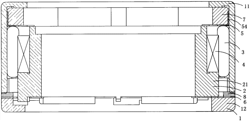
[0033] Figure 1 to Figure 5 A first embodiment of the invention is shown, in which figure 1 It is a schematic diagram of a three-dimensional structure of the first structure of the present invention; figure 2 for figure 1 A schematic diagram of the three-dimensional structure of the voice coil motor when viewed from another angle; image 3 for figure 1 A cross-sectional view of the voice coil motor shown; Figure 4 for figure 1 An exploded view of the voice coil motor shown; Figure 5 for figure 1 A schematic diagram of the three-dimensional structure of the upper shrapnel in the voice coil motor shown.
[0034] This embodiment is a lens driving device, see Figure 1 to Figure 5 , including a housing 1, and a lens carrier 2, a magnet assembly 3, a coil 4, an upper elastic piece 5, a lower elastic piece 6, an upper elastic piece bracket 7 and a lower insulating gasket 8 arranged in the housing 1; the lens carrier 2 is set Between the upper elastic piece 5 and the low...
Embodiment 2
[0045] Figure 6 and Figure 7 A second embodiment of the invention is shown in which, Figure 6 It is a cross-sectional view of the second structure of the present invention; Figure 7 for Figure 6 A schematic diagram of a three-dimensional structure of the magnet assembly shown.
[0046] This embodiment is basically the same as Embodiment 1, the difference is that: the magnet assembly 3 includes a plurality of magnets 31 arranged in a ring on the upper and lower layers, and the plurality of magnets 31 in the same layer are arranged in a ring, and the magnets in the same layer are arranged in a ring. There is a gap between adjacent two magnets 31; the upper end of each magnet 31 in the upper layer magnet 31 is an S pole, and the lower end is an N pole; the upper end of each magnet 31 of the lower floor is an N pole, and the lower end is an S pole; The coil 4 includes an upper coil and a lower coil, the upper coil is arranged directly above the lower coil, and there is a ...
Embodiment 3
[0049] Figure 8 It is a schematic diagram of the three-dimensional structure of the upper elastic piece in the third structure of the present invention, showing the third structure of the present invention
PUM
 Abstract
Description
Claims
Application Information
 - R&D
- Intellectual Property
- Life Sciences
- Materials
- Tech Scout
- Unparalleled Data Quality
- Higher Quality Content
- 60% Fewer Hallucinations
Browse by: Latest US Patents, China's latest patents, Technical Efficacy Thesaurus, Application Domain, Technology Topic, Popular Technical Reports.
© 2025 PatSnap. All rights reserved.Legal|Privacy policy|Modern Slavery Act Transparency Statement|Sitemap|About US| Contact US: help@patsnap.com