Rocking device for soothing babies
A rocking device and baby technology, which is applied in the field of rocking devices for comforting babies, can solve the problems of high production cost, small application range, and human injury, and achieve the effects of low production cost, low power consumption, and cost saving
- Summary
- Abstract
- Description
- Claims
- Application Information
AI Technical Summary
Problems solved by technology
Method used
Image
Examples
Embodiment 1
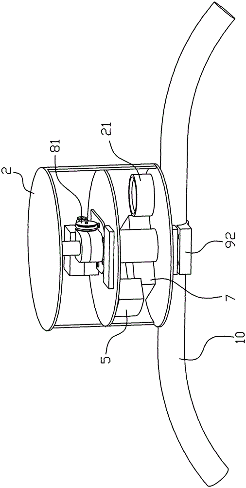
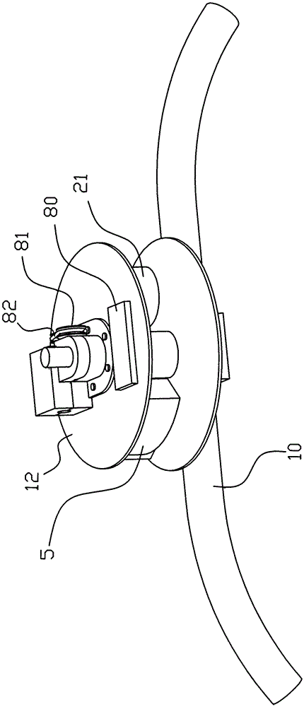
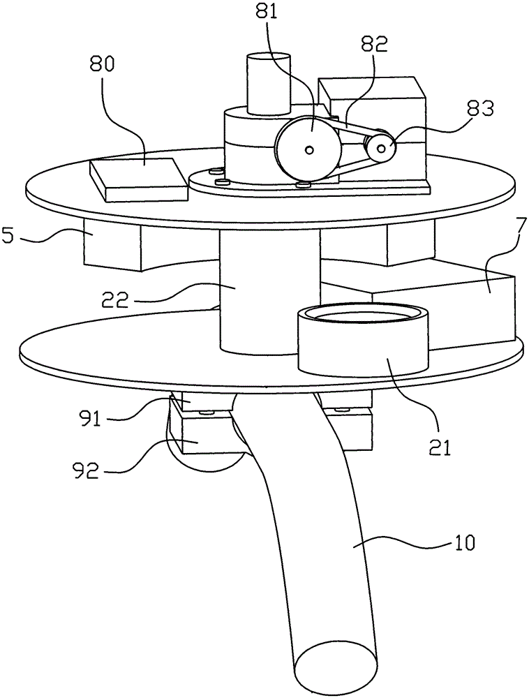
[0032] Embodiment one, such as Figure 1 to Figure 12 As shown, the rocking device of this embodiment includes a motor 1 and a housing 2 that can be fixed with the infant soothing device. The motor 1 is fixed on the partition 12 in the housing 2. The inner peripheral walls of the body 2 are fixed together. The output shaft 11 of the motor 1 is linked by a transmission device that can make the counterweight 51 rotate horizontally to generate centrifugal force and drive the vibration of the infant soothing device; the transmission device includes a rotating shaft 4 and a centrifugal block 5, and the centrifugal force One end of the block 5 is connected with the counterweight 51: the centrifugal block 5 is a sector block in the shape of a fan, the center end of the sector block is fixed to the rotating shaft 4, and the arc end of the sector block is provided with a top The arc-shaped concave cavity 52 of the opening, the counterweight 51 is inserted in the arc-shaped concave cav...
Embodiment 2
[0033] Embodiment two, such as Figure 13As shown, the rocking device of this embodiment is similar to the structure of the above rocking device, except that the structure of the device and the fixed rod 10 is detachable and fixed: the top of the housing 2 is provided with a concave cavity on the top surface A fixed plate 93 is provided above the fixed plate 93, and a paired plate 94 is provided. The bottom surface of the paired plate 94 is provided with a recessed portion. When the housing 2 and the fixed rod 10 are together, the fixed rod 10 is embedded in the recess. part and the recessed cavity, and the plywood 94 is fixed together with the fixing plate 93 by screws 95 or bolts.
Embodiment 3
[0034] Embodiment 3 is another structural embodiment of the present invention, its basic structure is the same as above, the difference is the centrifugal structure, see Figure 14 and Figure 15 As shown, the transmission device includes a rotating shaft 4 and a centrifugal block 5, and one end of the centrifugal block 5 is fixed to the rotating shaft 4 capable of horizontal rotation, and the other end of the centrifugal block 5 is connected to the rotating shaft 5 through a stay cord 50. The hanging ball 53 of the counterweight is connected, and the hanging ball 53 can make a horizontal circular motion around the inner cavity of the housing 2 under the drive of the rotating shaft 4 , which is linked with the output shaft 11 of the motor 1 .
PUM
 Abstract
Description
Claims
Application Information
 - R&D
- Intellectual Property
- Life Sciences
- Materials
- Tech Scout
- Unparalleled Data Quality
- Higher Quality Content
- 60% Fewer Hallucinations
Browse by: Latest US Patents, China's latest patents, Technical Efficacy Thesaurus, Application Domain, Technology Topic, Popular Technical Reports.
© 2025 PatSnap. All rights reserved.Legal|Privacy policy|Modern Slavery Act Transparency Statement|Sitemap|About US| Contact US: help@patsnap.com


