Method and system for adjusting vehicle imaging device

An image and adjustment technology, which is applied in closed-circuit television system, TV system components, image communication, etc., can solve the problems of inconvenient and impractical vehicle image devices, so as to improve driving safety, increase practicability and convenience sexual effect

Active Publication Date: 2013-03-13
深圳帷享科技有限公司
View PDF8 Cites 6 Cited by
  • Summary
  • Abstract
  • Description
  • Claims
  • Application Information

AI Technical Summary

Problems solved by technology

[0006] The purpose of the present invention is to overcome the defects existing in the existing vehicle imaging device, and provide a new method and system for adjusting the vehicle imaging device. The technical problem to be solved is to provide a vehicle calibration Use the method of image device, to overcome the problem that above-mentioned car image device is impractical and inconvenient
[

Method used


Image

  • Method and system for adjusting vehicle imaging device
  • Method and system for adjusting vehicle imaging device
  • Method and system for adjusting vehicle imaging device

Examples


Embodiment Construction

[0045] In order to further explain the technical means and effects of the present invention to achieve the intended purpose of the invention, the method and system for adjusting the vehicle image device according to the present invention will be described in detail below in conjunction with the accompanying drawings and preferred embodiments. , method, step, structure, feature and effect thereof, detailed description is as follows.

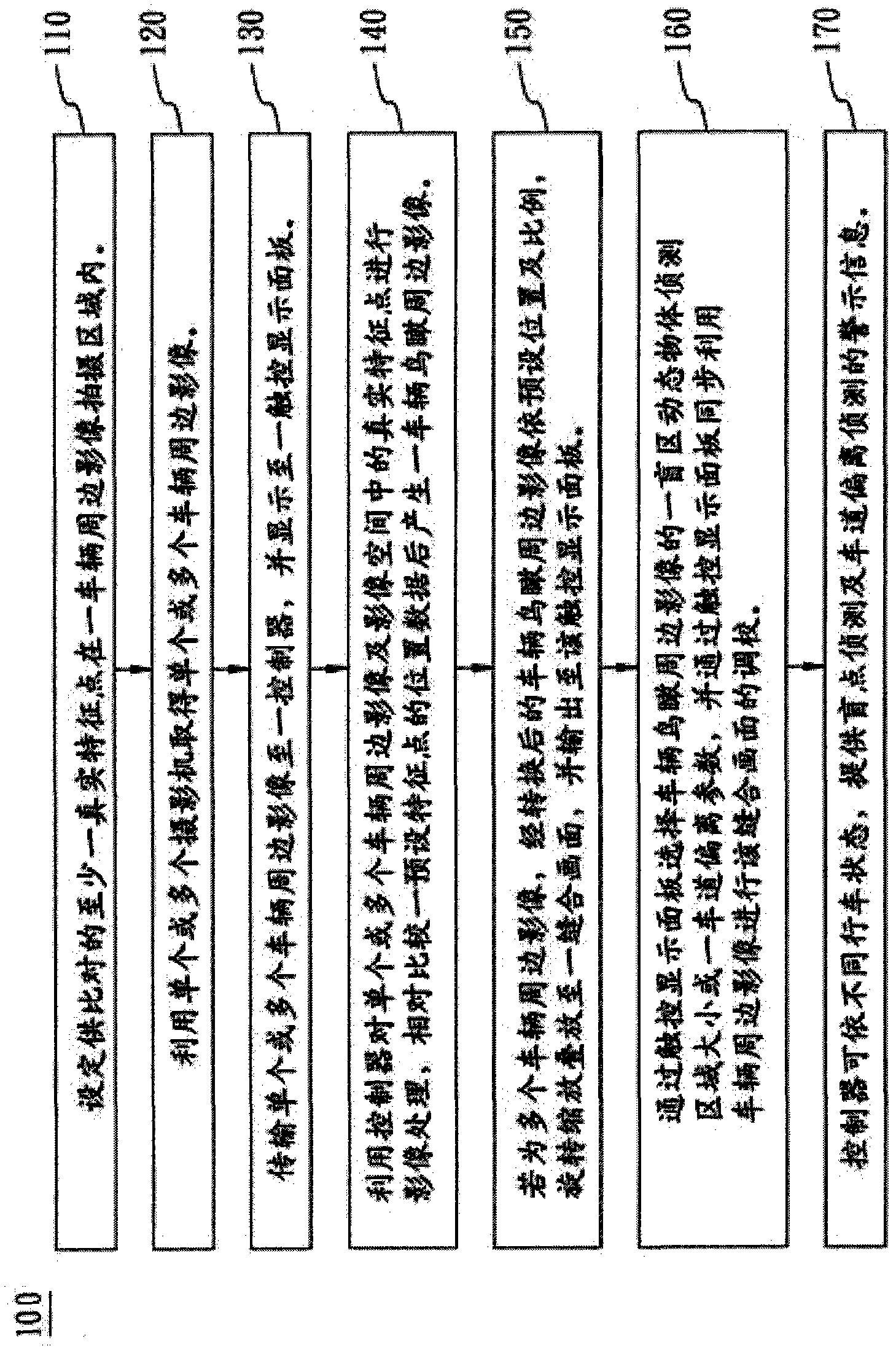
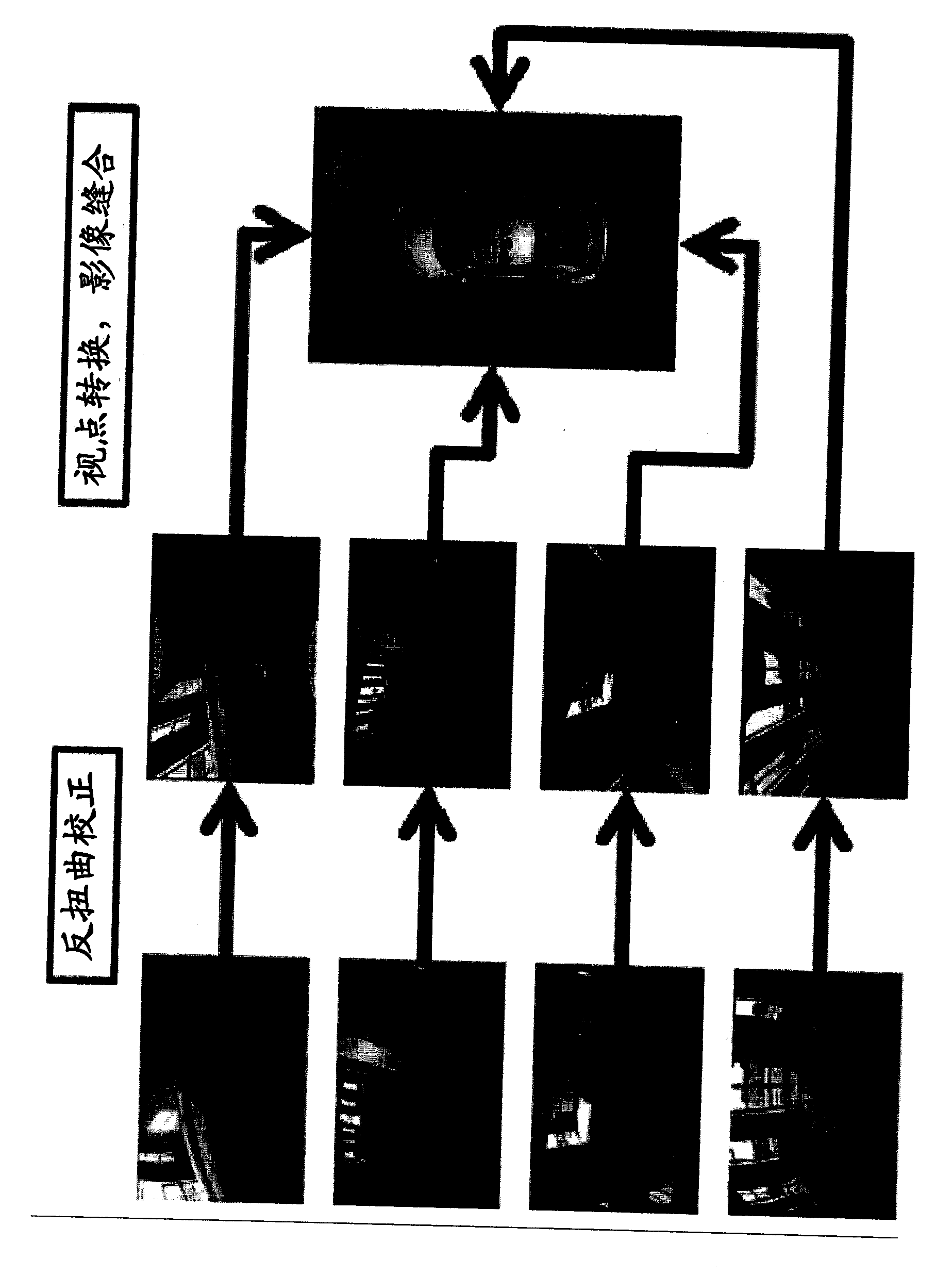
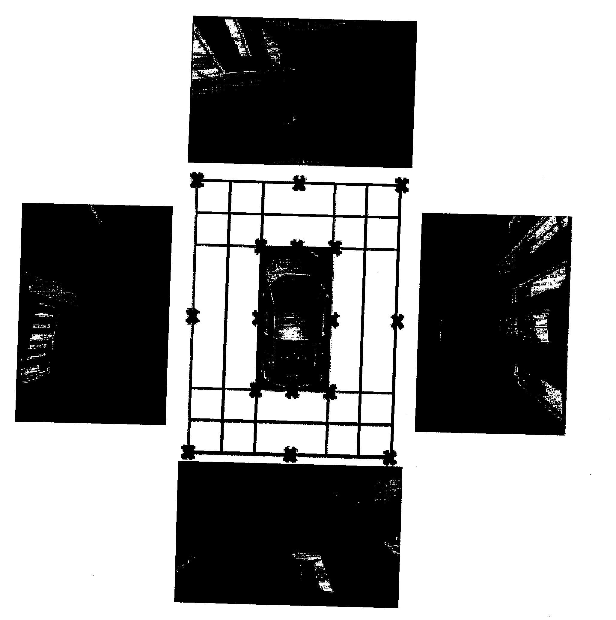
[0046] figure 1 A flow chart of the steps of the method for calibrating the bird's-eye view imaging device for vehicles according to an embodiment of the present invention is shown. Such as figure 1 As shown, the method for calibrating the bird's-eye view image device for a vehicle includes the following steps: Step 110, setting at least one real feature point for comparison to be within a vehicle peripheral image shooting area. Step 120, using single or multiple cameras to acquire single or multiple surrounding images of the vehicle. Step 130 ...


PUM


Abstract

The invention relates to a method for adjusting a vehicle bird's-eye viewed imaging device. The method comprises the following steps of arranging actual feature points in an image shooting area around a vehicle; utilizing one or more cameras to obtain images around the vehicle; transmitting the images to a controller and enabling the images to be displayed on a touch control display panel; utilizing the controller to process the images and the actual feature points, and comparing position data of preset feature points selected by the touch control display panel to generate bird's-eye viewed images around the vehicle; and enabling the bird's-eye viewed images around the vehicle to be rotatably zoomed to a stitching picture, and outputting the zoomed bird's-eye viewed images around the vehicle to the touch control display panel. The touch control display panel is used for adjusting the detection area of a dynamic object in a blind area or parameters of lane departure. The controller can provide blind point detection and lane departure detection warning information according to different vehicle running states.

Description

technical field [0001] The content of the present invention relates to a method for calibrating an image device for a vehicle, in particular to a method for calibrating an image device for a vehicle by means of a touch screen. According to the content of the present invention, warning information of blind spot detection and lane departure detection will be given to the driver according to different driving conditions. Background technique [0002] In terms of design concepts of modern vehicles, in addition to being used as a means of transportation for people, they also further pursue driving comfort, handling and safety, such as electronic anti-deadlock braking system (ABS), airbags, and vehicle imaging devices. Both provide an improved driving environment for users and passengers. [0003] The existing known vehicle imaging devices are cameras installed around the vehicle, which provide the user with knowledge of the rear and left and right conditions of the vehicle when ...

Claims


Application Information

Patent Timeline
IPC IPC(8): H04N5/14H04N5/232H04N7/18G06F3/0487
Inventor 罗圣杰陈加增王志远
Owner 深圳帷享科技有限公司
Why Eureka
Try Eureka