
micro speaker

A micro-speaker and voice coil technology, applied in the direction of sensors, electrical components, etc., can solve the problems of shortening the service life of the micro-speaker, poor electrical connection of the micro-speaker, and reducing the reliability of the micro-speaker, so as to achieve increased strength, not easy to break, and high strength Effect

Active Publication Date: 2015-12-02
GOERTEK INC
View PDF4 Cites 0 Cited by
  • Summary
  • Abstract
  • Description
  • Claims
  • Application Information

AI Technical Summary

Problems solved by technology

[0003] In the prior art, the voice coil lead wire of the miniature speaker is a tap of the wire for winding the voice coil. Since the wire for winding the voice coil is usually a thinner enameled wire, the toughness of the wire is poor. It is easy to cause the breakage of the voice coil lead, resulting in poor electrical connection of the micro-speaker, which seriously reduces the reliability of the micro-speaker and greatly shortens the service life of the micro-speaker

Method used


Image

  • micro speaker
  • micro speaker
  • micro speaker

Examples


Embodiment 1

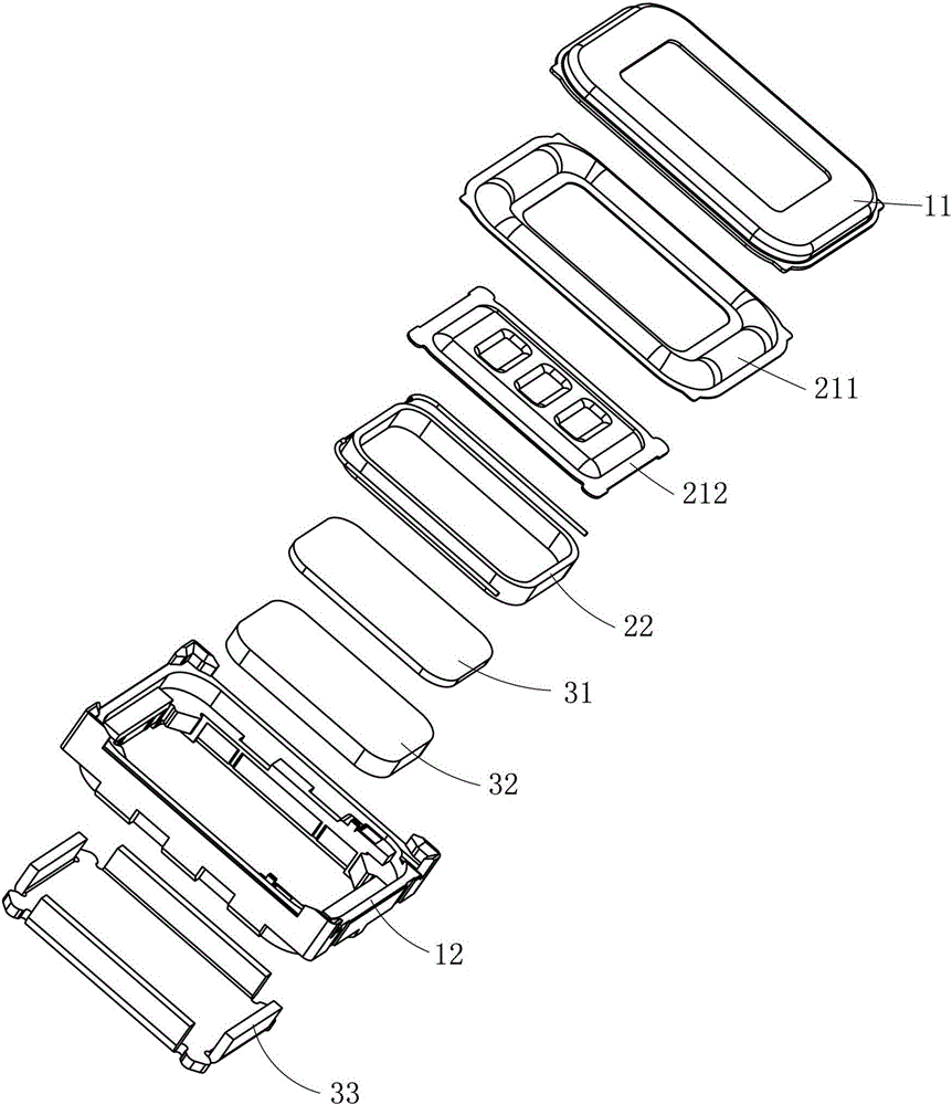
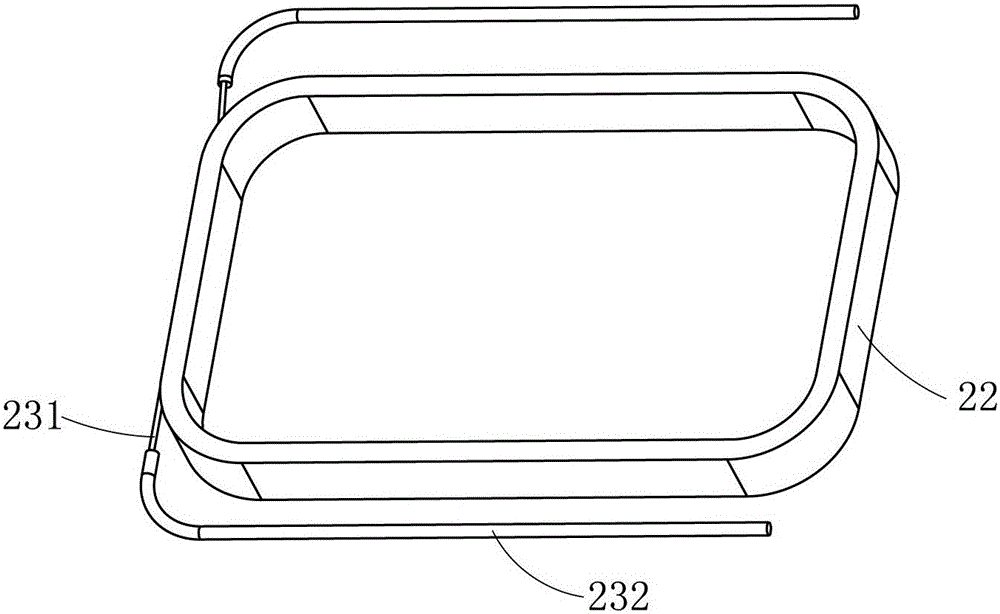
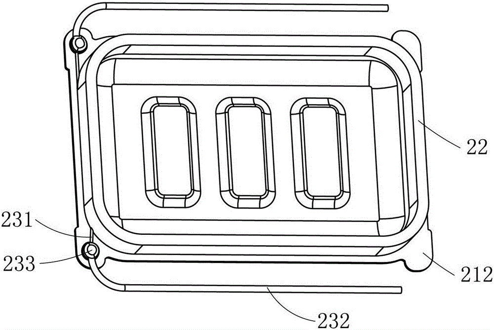
[0027] Such as figure 1 , figure 2 , image 3 and Figure 4 Commonly shown, a micro-speaker adopts a square structure, including a housing 12 and a front cover 11 combined with the housing 12. The voice coil outlet terminal 4 is provided on the housing 12, and the cavity surrounded by the housing 12 and the front cover 11 is accommodated. There are a vibration system and a magnetic circuit system. The vibration system includes a diaphragm and a voice coil 22. The leads of the voice coil 22 include a voice coil body lead 231 integrated with the voice coil 22. The voice coil body lead 231 is connected to the voice coil extension lead 232, and the voice coil extension The lead wire 232 is connected to the voice coil outlet terminal 4, and the material of the voice coil extension lead wire 232 is a conductive material with better toughness than the material of the voice coil body lead wire 231, such as brocade wire, enameled wire thicker than the voice coil body lead wire 231, ...

Embodiment 2

[0031] Such as Figure 5 , Figure 6 and Figure 7 Commonly shown, the main difference between this embodiment and Example 1 is: the micro-speaker is a circular structure, and the vibration system includes a diaphragm 21 and a voice coil 22; the magnetic circuit system includes a magnet 32 ​​arranged in the housing 12, and a There is Washi 31.

[0032] The wire bonding portion 233 where the voice coil body lead wire 231 and the voice coil extension lead wire 232 are connected is fixed on the side wall of the voice coil 22 . It can effectively prevent the lead wire of the voice coil from breaking at the lead wire bonding portion 233 when the voice coil 22 vibrates, further improves the reliability of the micro-speaker, and further prolongs the service life of the micro-speaker.


PUM


Abstract

The invention discloses a micro loudspeaker, and relates to the technical field of electroacoustic products. The micro loudspeaker comprises a housing and a front cover combined with the housing, wherein a vibrating system and a magnetic circuit system are accommodated in a cavity defined by the housing and the front cover; the vibrating system comprises a vibrating membrane and a voice coil; lead wires of the voice coil comprise a voice coil body lead wire integral with the voice coil; and the voice coil body lead wire is connected with a voice coil extension lead wire; the voice coil extension lead wire is made of a material the tenacity of which is better than that of the material of the voice coil body lead wire. By adopting the micro loudspeaker, the technical problem in the prior art that the voice coil lead wire of the micro loudspeaker is easily broken is solved. The voice coil lead wire of the micro loudspeaker disclosed by the invention is good in tenacity, good in strength, and not easily broken, thus improving the reliability of the micro loudspeaker, and prolonging the service of the micro loudspeaker.

Description

technical field [0001] The invention relates to the technical field of electroacoustic products, in particular to a micro speaker. Background technique [0002] With the rapid development of portable electronic products, micro-speakers, which are important acoustic devices in portable electronic products, have been widely used. The micro-speaker usually includes a vibration system and a magnetic circuit system housed in the casing. The vibration system includes a diaphragm and a voice coil arranged in sequence. The voice coil is connected to the voice coil outlet on the casing through the voice coil lead to connect the external circuit. The working principle of the micro-speaker is to feed the voice coil with alternating current, and under the action of the magnetic field generated by the magnetic circuit system, it will reciprocate relative to the magnetic circuit system. The voice coil drives the diaphragm to vibrate together, and the diaphragm drives the air to make a co...

Claims


Application Information

Patent Timeline
Patent Type & Authority Patents(China)
IPC IPC(8): H04R9/06H04R9/02
Inventor 刘春发蔡晓东葛连山徐同雁
Owner GOERTEK INC
Learn More