
Street lamp controller

A technology for controllers and street lamps, applied in energy-saving control technology, lamp circuit layout, lighting devices, etc., can solve problems such as limitations, high cost of networked control, and high price of GPRS modules, and achieve low cost, power saving, and networked control low cost effect

Inactive Publication Date: 2013-03-13
ZHEJIANG WANLI UNIV
View PDF3 Cites 3 Cited by
  • Summary
  • Abstract
  • Description
  • Claims
  • Application Information

AI Technical Summary

Problems solved by technology

[0002] In the prior art, most street lamps are equipped with street lamp controllers, which are used to control the switch and brightness of street lamps, etc. Most of these street lamp controllers simply control the switch of street lamps through photoelectric detection, and automatically turn on the street lamps when the environment is dark. Turn off the street lights automatically when they are on. This control method is relatively simple and cannot well adapt to the energy-saving needs of different road sections. In terms of actual road conditions, some road sections have few pedestrians, and the street lights are always on, which is a waste of electricity. need to stay on
At the same time, most of the street lamp controllers in the prior art do not have the network control function, and some controllers with the network control function are realized through the GRPS module. The module communicates with the general street lamp control center, so that each street lamp controller must be equipped with a GPRS module, the price of the GPRS module is very high, and the GPRS module needs to pay the communication fee to the operator during the operation process, and the implementation cost is high , the control is not flexible, especially in some places where the signal is not good, the networked large-area application is greatly restricted
To sum up, the street lamp controllers in the prior art have the disadvantages of a single control method, which cannot well adapt to the energy-saving needs of different road sections, and high cost of networked control.

Method used


Image

  • Street lamp controller
  • Street lamp controller
  • Street lamp controller

Examples


Embodiment Construction

[0024] The present invention will be described in further detail below in conjunction with the accompanying drawings.

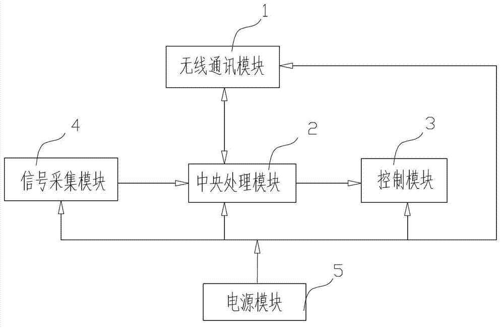
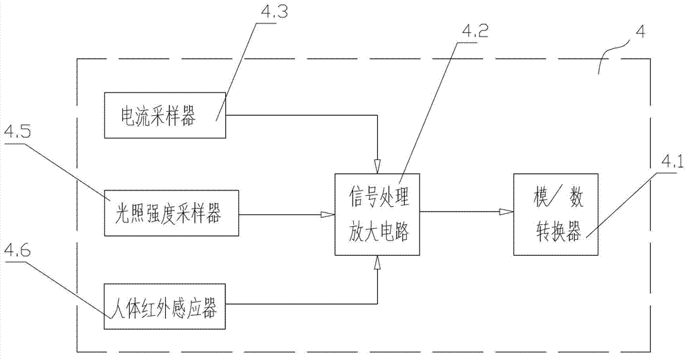
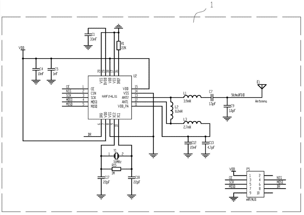
[0025] combined with figure 1 to attach Figure 9, a street lamp controller, which includes a street lamp controller used to communicate with adjacent street lamp controllers (adjacent refers to other street lamp controllers located within the coverage of wireless communication signals around it, because street lamps are used one by one in specific use) Installed along the roadside according to the array, each street lamp needs to be installed with one of the street lamp controllers, and the adjacent street lamps are generally the street lamp controllers on the adjacent street lamps before and after the street lamp where the street lamp controller is located. Wireless communication module 1 for communication, central processing module 2, power supply module 5, control module 3 for controlling the opening and closing of street lamps, and signal acquisition mo...


PUM


Abstract

The invention relates to a street lamp controller which is characterized by comprising a wireless communication module (1), a central processing module (2), a power source module (5), a control module (3) and a signal acquisition module (4). The wireless communication module (1), the central processing module (2), the control module (3) and the signal acquisition module (4) are electrically connected with the power source module (5); the central processing module (2) is respectively and electrically connected with the wireless communication module (1), the control module (3) and the signal acquisition module (4); the signal acquisition module (4) comprises a current signal processing submodule (6) and a photo-induction submodule (7); and a communication chip adopted by the wireless communication module (1) is a radio frequency chip. The street lamp controller can well adapt to energy-saving requirements of different road sections and is controlled in networking mode and low in cost.

Description

technical field [0001] The invention relates to the technical field of street lamp control, in particular to a street lamp controller. Background technique [0002] In the prior art, most street lamps are equipped with street lamp controllers, which are used to control the switch and brightness of street lamps, etc. Most of these street lamp controllers simply control the switch of street lamps through photoelectric detection, and automatically turn on the street lamps when the environment is dark. Turn off the street lights automatically when they are on. This control method is relatively simple and cannot well adapt to the energy-saving needs of different road sections. In terms of actual road conditions, some road sections have few pedestrians, and the street lights are always on, which is a waste of electricity. It needs to be on all the time. At the same time, most of the street lamp controllers in the prior art do not have the network control function, and some contro...

Claims


Application Information

Patent Timeline
IPC IPC(8): H05B37/02
CPCY02B20/40Y02B20/72
Inventor 薛立新
Owner ZHEJIANG WANLI UNIV
Learn More