Safe self-destruction type injector

A syringe and self-destruction technology, applied in the field of medical devices, can solve the problems of difficult manufacturing process, unsatisfactory effect, high material requirements, etc., and achieve the effects of low manufacturing process difficulty, easy promotion and reduction of process steps.

Inactive Publication Date: 2013-03-20
田凌晖
View PDF0 Cites 0 Cited by
  • Summary
  • Abstract
  • Description
  • Claims
  • Application Information

AI Technical Summary

Problems solved by technology

[0004] In order to avoid the occurrence of the above-mentioned incidents, there are currently some safety syringes in which the needle holder is arranged in the barrel neck, and the needle holder can be pulled into the needle barrel after use. The basic design structure of this type of safety injection is A metal hook is added to the front end of the core rod piston, or a barb is connected to the lower end of the needle seat. After the injection is completed, the needle seat can be pulled back into the syringe by the pulling force of the metal hook to achieve safety purposes, but its There are certain shortcomings in the design structure: 1. The simple metal hook structure has a high error rate when used, and the stability is poor when used in batches, and the effect is not very ideal in actual use; 2. The structure of this type of metal hook is fine, The manufacturing process is difficult and requires high materials, which leads to an increase in production costs, and it is easy to cause some inferior products on the market

Method used


Image

  • Safe self-destruction type injector
  • Safe self-destruction type injector
  • Safe self-destruction type injector

Examples


Embodiment Construction

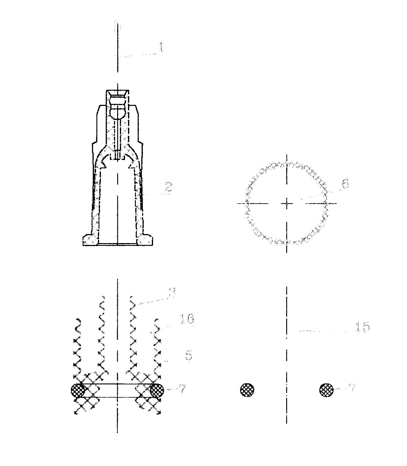
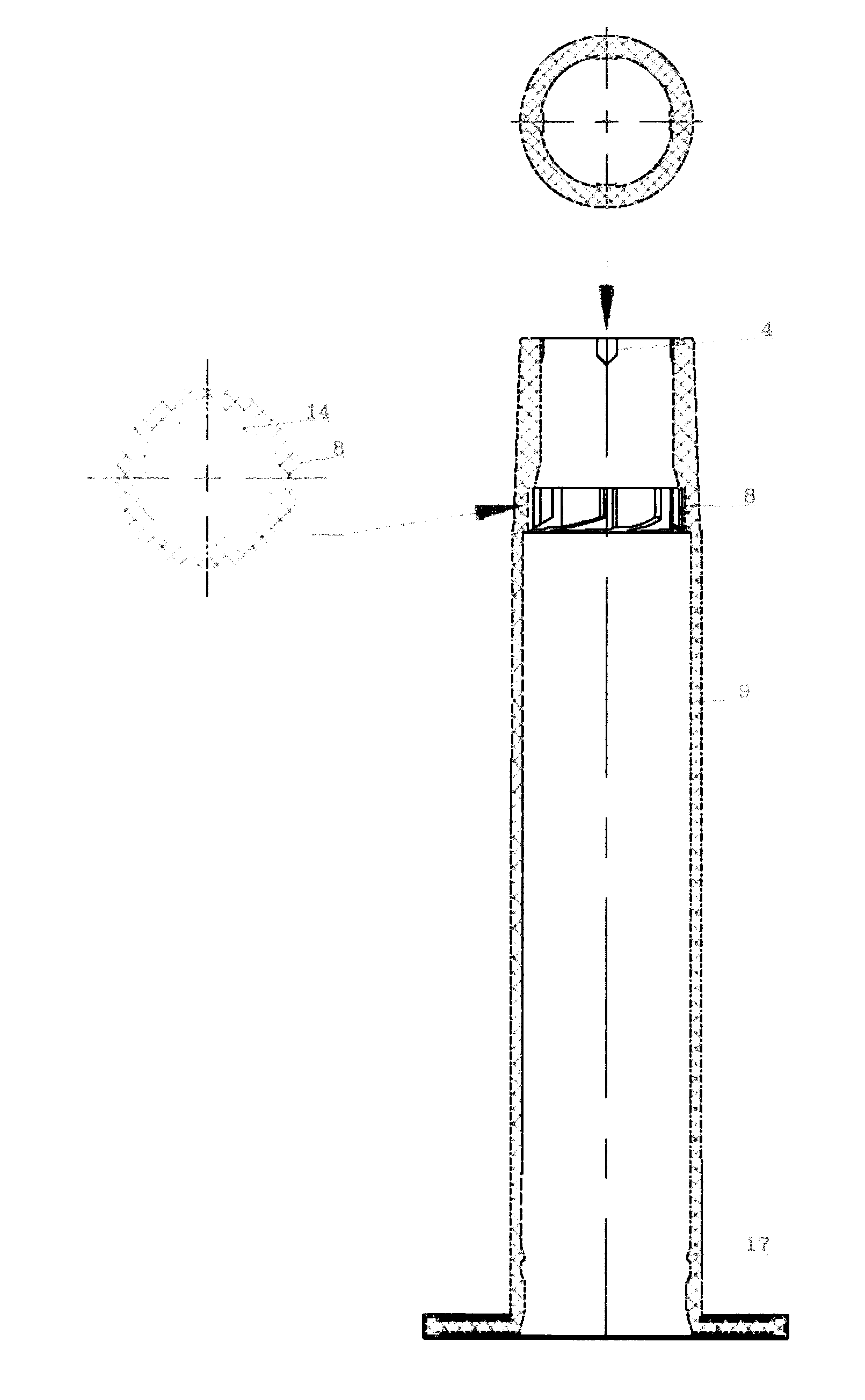
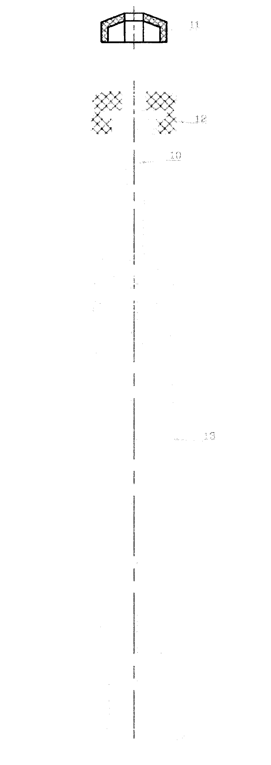
[0018] Below in conjunction with accompanying drawing and embodiment this patent is further described.

[0019] Such as figure 1 , figure 2 , image 3 , Figure 4 As shown in: the present invention mainly includes an injection needle (1); a needle seat (2); a 6:100 tapered hole (3) on the replaceable needle seat; a fixed anti-slip strip (4) on the barrel; the replaceable needle Seat (5); pull-back piece (6) on the replaceable needle seat; sealing ring (7); cylinder neck (8); cylinder body (9); pull-back connecting column (10); piston fixing seat (11) ;piston (12); core rod (13); outer shrapnel (14); fixed anti-skid groove (15) on the replaceable needle seat; fixed thread (16) on the replaceable needle seat; The rod pushes back and pulls out the ring (17); the non-threaded replaceable needle seat (18); the fixed needle needle seat (19), which is different from the prior art in that:

[0020] (1), the cylinder neck (8) above the cylinder (9) is provided with an outer shrap...


PUM


Abstract

The invention discloses a safe self-destruction type injector. Compared with the prior art, the safe self-destruction type injector is characterized by comprising a needle cylinder, an extension shrapnel which is arranged on the inner neck portion of the needle cylinder, a core pin, a piston which is sleeved at the upper end of the core pin, a piston fixing seat, a replaceable needle head seat which is matched with the cylinder body and can be pulled back, a seal ring, a needle seat and an injection needle. The replaceable needle head seat is fixed and the rear portion of the replaceable needle head seat is matched with the extension shrapnel which is arranged on the inner neck portion of the needle cylinder. When an injection is close to an ending, the piston fixing seat at the front end of the core pin pushes the extension shrapnel on the inner neck portion of the needle cylinder outwards. When the injection is finished, a back-pulling connecting column at the front end of the core pin successfully pulls the needle head seat back to the cylinder body. A ring preventing the core pin from back pushing and pulling out on the cylinder body and a locking core pin prevent the core pin from moving forward and pulling backward. The safe self-destruction type injector breaks the traditional design philosophy of the injector. The safe self-destruction type injector has the advantages of being reasonable in structural design, high in safety, low in difficulty of manufacturing technique, few in process, saving in cost, easy to manufacture and easy to popularize.

Description

Technical field: [0001] The patent of the present invention relates to the technical field of medical devices, specifically a safety self-destruction syringe with a replaceable needle and a needle seat, which can be pulled back. Background technique: [0002] Unsafe injections include misuse of injections, unsterilized syringes, reuse of disposable syringes, improper waste disposal, operational contamination, preparation contamination, etc. According to incomplete statistics, unsafe injections cause 21.7 million people to be infected with hepatitis B virus, 2 million people to be infected with hepatitis C virus, 96,000 people to be infected with HIV, 1.3 million people to die prematurely, and direct medical expenses to reach 535 million US dollars. [0003] Since the first report on the harm of needlestick injuries to medical staff in 1981, a large number of studies on the characteristics of "occupational exposure of medical staff" have been carried out internationally. hig...

Claims


Application Information

Patent Timeline
Patent Type & Authority Applications(China)
IPC IPC(8): A61M5/50A61M5/315A61M5/32
Inventor 周明雄
Owner 田凌晖
Why Eureka
Try Eureka