
Medical full-automatic cleaning machine with floating ball valve

A fully automatic cleaning and floating ball valve technology, which is applied in the direction of engine components, control valve floats, valve operation/release devices, etc., can solve the problems of high cost of solenoid valves, easy failure of one-way mechanical valves, energy consumption, etc.

Active Publication Date: 2013-03-20
LAOKEN MEDICAL TECH
View PDF8 Cites 4 Cited by
  • Summary
  • Abstract
  • Description
  • Claims
  • Application Information

AI Technical Summary

Problems solved by technology

In order to prevent hot air from entering the water pump and hot water from entering the air pump, a check valve is installed at the end of the air pump pipe and the end of the water pump pipe in the prior art to prevent hot water from entering the air pump and damage the air pump, and prevent hot air from entering the water pump. To accelerate the aging of the water pump, the two check valves set in the prior art are generally solenoid valves or one-way mechanical valves. The solenoid valve has a relatively complicated electrical structure because of its high cost and the need to rely on electrical methods to control the opening and closing of the valve. , so less and less are used now, and now most of them use two ordinary one-way mechanical valves, but the ordinary one-way mechanical valves in the prior art need to be arranged horizontally to be effective, and the main pipes of the washing machine are all Vertically arranged, so in the prior art, a horizontal pipe is respectively connected to the upper and lower ends of the main pipe as the starting end of the air pump or water pump, and two mechanical check valves are installed at the starting end respectively. Although the horizontal pipe end can achieve the one-way sealing effect of hot air or hot water, the hot water or hot air needs to go through a 90-degree elbow to be sent to the main pipe, which consumes part of the energy, and the single Directional mechanical valves are prone to failure after frequent use

Method used


Image

  • Medical full-automatic cleaning machine with floating ball valve
  • Medical full-automatic cleaning machine with floating ball valve
  • Medical full-automatic cleaning machine with floating ball valve

Examples


Embodiment Construction

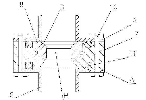
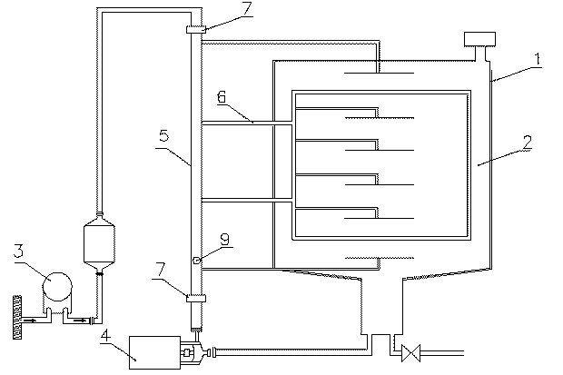
[0020] like Figure 1 to Figure 5 As shown, the first specific embodiment of the present invention is: a medical automatic cleaning machine with a float valve, comprising a frame 1, a cleaning chamber 2, an air pump 3, a water pump 4 and a main pipeline 5, the frame 1, Both the cleaning chamber 2 and the main pipeline 5 are made of stainless steel, and a cleaning frame is arranged in the cleaning chamber 2, and the main pipeline 5 is arranged outside the cleaning chamber 2 and vertically arranged on the frame 1 parallel to the side wall of the cleaning chamber. Both the air pump 3 and the water pump 4 are installed on the frame 1, the air pump 3 is connected to the upper end of the main pipeline 5, and the water pump 4 is connected to the lower end of the main pipeline and connected to the water tank below the cleaning chamber 2, and is installed on the cleaning chamber and the cleaning rack. A plurality of spouts are provided, and these spouts communicate with the main pipe 5...


PUM


Abstract

The invention discloses a medical full-automatic cleaning machine with a floating ball valve. The medical full-automatic cleaning machine comprises a rack (1), a cleaning cabin (2), an air pump (3), a water pump (4) and a main pipeline (5), wherein the cleaning cabin (2) is internally provided with a cleaning rack, the air pump (3) is connected with the upper end of the main pipeline (5), the water pump (4) is connected with the lower end of the main pipeline (5), the cleaning cabin and the cleaning rack are provided with multiple spray nozzles respectively, the multiple spray nozzles are communicated with the main pipeline (5) through multiple branch pipelines (6), two valve seats (7) are respectively arranged at the connecting parts between the main pipeline (5) and the air pump (3) as well as between the main pipeline (5) and the water pump (4), the main pipeline between the two valve seats (7) is internally provided with a the valve ball (9), the valve ball (9) can be respectively in tight contact with one valve seat which is arranged above or under the main pipeline under the drive of water pressure or wind force, and thus a one-way sealing ball valve can be formed. According to the medical full-automatic cleaning machine disclosed by the invention, the structure is simple, the sealing is reliable, and the double-position one-way sealing of the air pump and the water pump can be realized just by virtue of one valve ball.

Description

technical field [0001] The invention relates to a medical cleaning and disinfection equipment, in particular to a medical full-automatic washing machine, in particular to a valve mechanism for controlling the water and air supply of the medical full-automatic washing machine. Background technique [0002] The medical automatic cleaning machine is mainly used for cleaning and disinfection of medical equipment, such as cleaning and disinfection of various surgical instruments and utensils after hospital operations. The specific cleaning method is to put the medical equipment to be cleaned in the cleaning machine. Rack, and heat the washing water that has been added with enzyme liquid, then use the water pump to pressurize the washing water, spray the washing hot water on the medical equipment to be cleaned with a higher water pressure, and then use the air pump to Hot air with a temperature exceeding 100°C is sent into the cleaning chamber to dry the cleaned medical devices. I...

Claims


Application Information

Patent Timeline
IPC IPC(8): B08B3/02F16K15/04F16K33/00F16K31/18
Inventor 刘勇张聪青奉李徐鸿喻安义羊肇雄赖永聪刘巍
Owner LAOKEN MEDICAL TECH
Learn More