
Electric vehicle chassis system and collaborative control method thereof

An electric vehicle and vehicle braking technology, applied in the field of electric vehicle chassis system and its collaborative control, can solve the problems of complex controller design, difficult to guarantee the overall reliability, shortening the development time of the controller and the difficulty of development, so as to improve the smooth driving sex, reducing conflicting effects

Inactive Publication Date: 2013-03-20
BEIJING UNIV OF TECH
View PDF9 Cites 11 Cited by
  • Summary
  • Abstract
  • Description
  • Claims
  • Application Information

AI Technical Summary

Problems solved by technology

At present, the integrated control structure of the automobile chassis system mainly has two types: centralized and hierarchical. The controller is highly integrated, and the control effect is usually good, but there are problems such as complicated controller design and difficulty in ensuring the overall reliability; the layered type is to design an upper-level control system under the premise of keeping the original subsystem controller unchanged. The controller is used to monitor and control each sub-controller, so as to coordinate the coupling subsystems. Using this structure can shorten the development time of the controller, reduce the difficulty of development, and usually obtain better integrated control effects, but it needs to be designed Familiar with the coupling process of subsystems

Method used


Image

  • Electric vehicle chassis system and collaborative control method thereof
  • Electric vehicle chassis system and collaborative control method thereof
  • Electric vehicle chassis system and collaborative control method thereof

Examples


Embodiment Construction

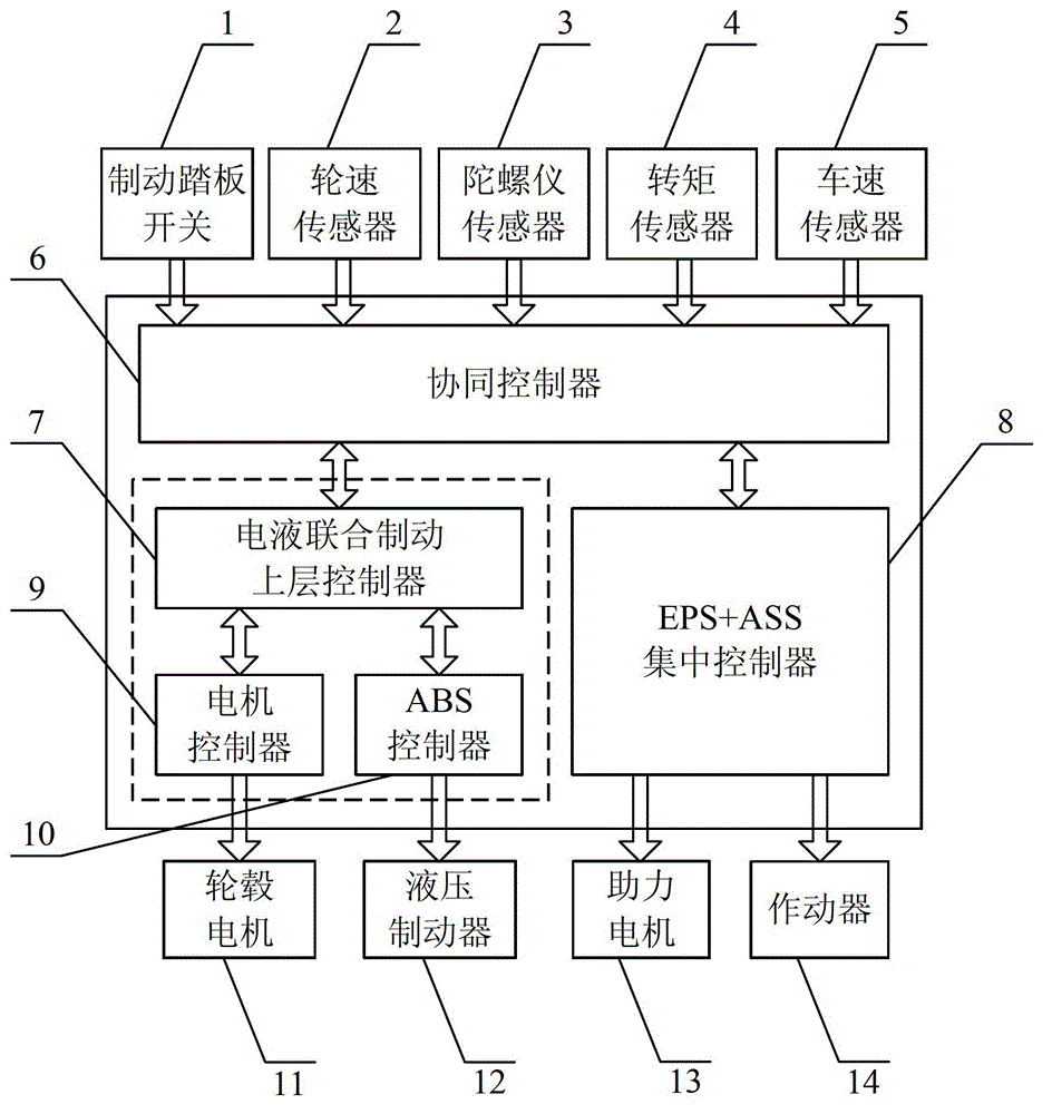
[0011] The present embodiment will be further described in conjunction with FIG. 1 .

[0012] The electric vehicle chassis system of the present invention is composed of EPS, ASS, ABS and motor braking system, which respectively represent the three subsystems of steering system, suspension system and braking system in the electric vehicle chassis system.

[0013] In the present invention, the brake pedal switch 1 generates a brake trigger signal, the wheel speed sensor 2 measures the wheel speed signal, and the gyro sensor 3 measures the vertical acceleration, longitudinal acceleration, lateral acceleration, pitch angle, roll angle and The yaw rate signal, the torque sensor 4 measures the steering shaft input torque signal, the vehicle speed sensor 5 measures the vehicle speed signal, and the above sensor signals are transmitted to the cooperative controller 6; the cooperative controller 6 transmits the brake trigger signal, wheel speed signal, The vehicle speed signal and the...


PUM


Abstract

The invention discloses a collaborative control method of an electric vehicle chassis system and relates to the field of vehicle control. The collaborative control method is characterized in that a brake trigger signal, a wheel speed signal, a vehicle body vertical acceleration signal, a longitudinal acceleration signal, a lateral acceleration signal, a pitching angle signal, a heeling angle signal, a heading angle speed signal, a steering shaft input torque signal and a vehicle speed signal which are measured by sensors are transmitted to a collaborative controller, the collaborative controller monitors the running state of a vehicle and gives out control commands to an electro-hydraulic combined brake upper controller and an EPS (electric power steering)+ASS (active suspension system) centralized controller, the electro-hydraulic combined brake upper controller and the EPS+ASS centralized controller operate according to respective received sensor signals and collaborative controller commands, the electro-hydraulic combined brake upper controller controls in-wheel motors and hydraulic brake units by coordinating a motor controller and an ABS (anti-lock braking system) controller, and the EPS+ASS centralized controller directly controls power-assisting motors and actuators. The collaborative control method of the electric vehicle chassis system has the advantages that the conflict under a subsystem coupling condition is reduced and the overall performance of the electric vehicle chassis system is improved.

Description

technical field [0001] The invention relates to an electric vehicle chassis system and a cooperative control method thereof, belonging to the technical field of electric vehicle cooperative control. Background technique [0002] With the rapid development of the automobile industry, the decentralized independent control of each subsystem in the automobile chassis system can no longer meet people's increasing requirements for the overall performance of the automobile. The integrated control of the automobile chassis system has become a research hotspot in the current automobile chassis control. Compared with the traditional vehicle chassis system, the electric vehicle chassis system only simplifies the transmission system, and adds a motor brake system to the braking system, so the integrated control of the electric vehicle chassis system can be based on the integrated control of the traditional vehicle chassis system. At present, the integrated control structure of the autom...

Claims


Application Information

Patent Timeline
IPC IPC(8): B60W30/00B60W10/20B60W10/184B60W10/22B60W40/105B60W40/10
Inventor 冯能莲彭剑坤宾洋占子奇高翔
Owner BEIJING UNIV OF TECH
Features
  • Generate Ideas
  • Intellectual Property
  • Life Sciences
  • Materials
  • Tech Scout
  • Unparalleled Data Quality
  • Higher Quality Content
  • 60% Fewer Hallucinations
Learn More