Installation structure convenient for disassembling and assembling expansion joint of heat transfer casing

An installation structure and technology of expansion joints, which are applied to expansion compensation devices for pipelines and protect pipelines and pipes through thermal insulation, can solve the problems of difficulty in installation and disassembly of expansion joints, solve inconvenient installation and disassembly, reduce heat Stress and force, loss reduction effect

Active Publication Date: 2013-03-20
SHAANXI XIXIAN NEW AREA FENGXI NEW CITY ENERGY DEV CO LTD
View PDF5 Cites 5 Cited by
  • Summary
  • Abstract
  • Description
  • Claims
  • Application Information

AI Technical Summary

Problems solved by technology

[0003] In order to meet the needs of the new heat transfer pipeline system, the purpose of the present invention is to provide an installation structure that facilitates the disassembly and assembly of the expansion joint of the heat transfer sleeve, which solves the problem of difficult installation and disassembly of the expansion joint of the new heat transfer piping system, and at the same time, when the expansion joint When damaged, the maintenance and replacement of the expansion joint is facilitated, and the loss caused by untimely maintenance and replacement is reduced; the invention increases the practicability of the heat transfer sleeve system and promotes its further development and application

Method used


Image

  • Installation structure convenient for disassembling and assembling expansion joint of heat transfer casing
  • Installation structure convenient for disassembling and assembling expansion joint of heat transfer casing
  • Installation structure convenient for disassembling and assembling expansion joint of heat transfer casing

Examples


Embodiment Construction

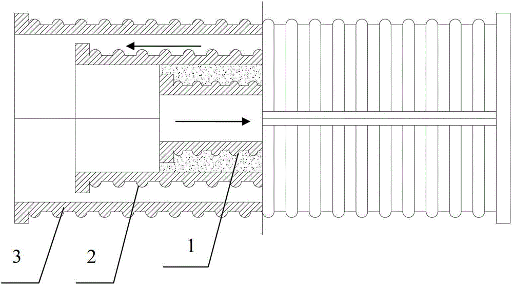
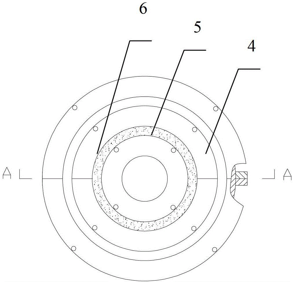
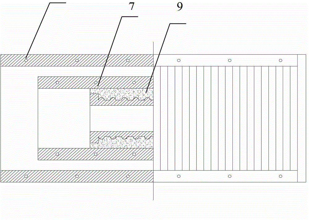
[0019] Such as figure 1 , figure 2 and image 3 As shown, the present invention is an installation structure that facilitates the disassembly and assembly of the thermowell expansion joint. There is an expansion joint inner tube 1 with a smaller diameter in the expansion joint outer tube 3 with a larger diameter, and an expansion joint inner tube 1 outside the expansion joint. The thermal insulation cotton layer 9, the thermal insulation cotton layer 9 coats the expansion joint intermediate pipe 2, in order to absorb the thermal expansion of the inner and outer expansion joints, there is a gap between the expansion joint inner pipe 1 and the expansion joint intermediate pipe 2. The hot fluid conveyed by the inner pipe of the heat transfer pipe system flows in the inner pipe 1 of the expansion joint, and the cold fluid returned by the heat transfer pipe system flows in the annular space between the middle pipe 2 of the expansion joint and the outer pipe 3 of the expansion joi...


PUM


Abstract

The invention discloses an installation structure convenient for disassembling and assembling an expansion joint of a heat transfer casing. The installation structure comprises an expansion joint inner pipe, an expansion joint middle pipe and an expansion joint outer pipe which are arranged in sequence from inside to outside, wherein the expansion joint inner pipe is connected with an inner pipe of the heat transfer casing through an inner ring flange; the expansion joint middle pipe is connected with a middle pipe of the heat transfer casing through a middle ring flange; the expansion joint outer pipe is connected with an outer pipe of the heat transfer casing through an outer ring flange; two parts of the expansion joint middle pipe are connected with each other through a middle pipe connecting flange; and two parts of the expansion joint outer pipe are connected with each other through an outer pipe connecting flange. Due to the adoption of the installation structure, the problem of difficulty in installing and detaching an expansion joint of a novel heat transfer pipeline system is solved; meanwhile, when the expansion joint is damaged, convenience is brought to maintenance and replacement of the expansion joint, and losses caused by untimely maintenance and replacement are reduced; and the practicability of a heat transfer casing system is enhanced, and further development and application of the heat transfer casing system are propelled.

Description

technical field [0001] The invention relates to a heat transfer sleeve structure connected with a pipeline system, in particular to an installation structure for facilitating the disassembly and assembly of the expansion joint of the heat transfer sleeve. Background technique [0002] Chinese patent ZL201110102653.7, titled: A new type of high-efficiency energy-saving heat transmission three-layer pipeline system, the high-efficiency energy-saving heat transmission pipeline system can effectively reduce the heat loss of the pipeline for transporting hot fluid and transfer this part of heat loss to the return flow of cold fluid. Back, the heat dissipation loss is greatly reduced, and the system has a compact structure, a relatively simple process, and high reliability. As a compensation flexible structure, the expansion joint is connected with a new type of high-efficiency energy-saving heat transfer three-layer pipeline by traditional welding, and there are many deficiencies...

Claims


Application Information

Patent Timeline
Patent Type & Authority Applications(China)
IPC IPC(8): F16L9/19F16L51/00F16L39/04F16L59/21
Inventor 邱霞吴东垠王利兵赫永鹏闫建武许奎
Owner SHAANXI XIXIAN NEW AREA FENGXI NEW CITY ENERGY DEV CO LTD
Why Eureka
Try Eureka