Light emitting diode (LED) lamp with convection channel penetrating through light source baseplate

A technology of LED lamps and light source substrates, applied in the field of LED lamps, can solve the problems that the central part of the radiator cannot form air convection and the temperature of the central part of the light source is high

Inactive Publication Date: 2013-03-20
黄超
View PDF8 Cites 12 Cited by
  • Summary
  • Abstract
  • Description
  • Claims
  • Application Information

AI Technical Summary

Problems solved by technology

So as to solve the problems of light decay and air convection in the central part of the radiator caused by the

Method used


Image

  • Light emitting diode (LED) lamp with convection channel penetrating through light source baseplate
  • Light emitting diode (LED) lamp with convection channel penetrating through light source baseplate
  • Light emitting diode (LED) lamp with convection channel penetrating through light source baseplate

Examples


Embodiment 1

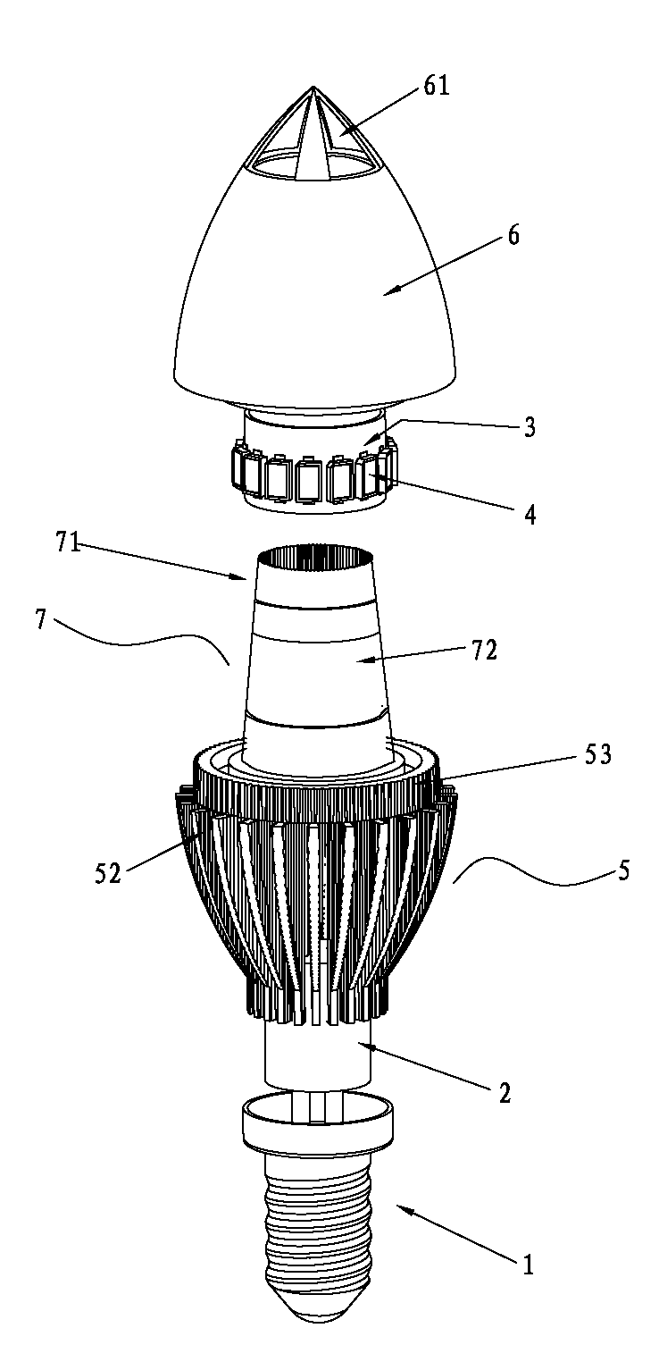
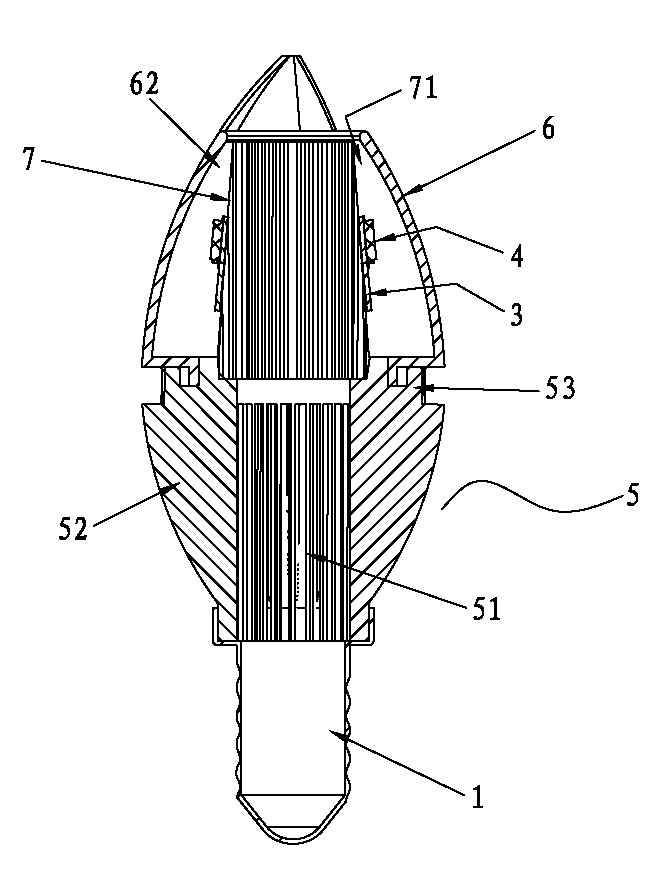
[0020] Such as figure 1 , figure 2 , image 3 As shown, an LED lamp with a convection channel passing through the light source substrate includes a lamp holder 1, an LED driver 2, an LED substrate 3, an LED light source 4, a finned radiator 5 and a lampshade 6 and is fixedly connected. The LED light source 4 is arranged on On the LED substrate 3 , the LED lamp head is connected to one end of the finned radiator 5 , and the lampshade 6 is connected to the other end of the finned radiator 5 . The LED driver 2 is arranged on one end of the finned heat sink 5 with the LED lamp cap 1 and is electrically connected with the LED lamp cap 1; The guide tube 7 extends into the lampshade 6, and there is a gap between two adjacent cooling fins 52 of the finned radiator 5, which communicates with the inner cavity 51 of the finned radiator 5;

[0021] The top of the lampshade 6 has a guide hole 61 , and the guide hole 61 is opposite to the suspended end of the heat dissipation guide pipe...

Embodiment 2

[0028] Such as Figure 4 , Figure 5 , Figure 6 As shown, the LED substrate 3 is in the shape of a circular disc, the heat dissipation duct 7 passes through the LED substrate 3 , and the LED substrate 3 is bonded to the annular seat 53 of the finned heat sink 5 . The LED substrate 3 cooperates with the end of the central tube 51 at the connecting end of the finned heat sink 5 and the lampshade 6 .

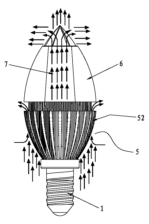
[0029] Figure 5 It is the front view of the present invention when it is hoisted. Cold air passes through the inner cavity of the guide hole 61 on the lampshade, the heat dissipation guide tube 7, and the finned radiator 5, and dissipates heat rapidly through the gap between two adjacent fins.


PUM


Abstract

A light emitting diode (LED) lamp with a convection channel penetrating through a light source baseplate comprises a lamp head, an LED drive, an LED light source baseplate, an LED light source, a fin chip type radiator and a lamp cover. The end, connected with the lump cover, of the fin chip type radiator extends and a radiating deflector tube is formed. The radiating deflector tube inserted into the lump cover, penetrates through the lamp cover and is connected with a position of a center air hole of the lamp cover. Gaps are formed between two adjacent radiating fin chips of the fin chip type radiator and are communicated with a cavity of the fin chin type radiator. A deflector hole is formed in the top of the lamp cover. The deflector hole is opposite to a suspension end of the radiating deflector tube. According to the structure, a radiating circulation channel is formed by gaps between the two adjacent radiating fin chips, the fin chip type radiator, the radiating deflector tube and the deflector hole of the lamp cover. Vertical air cross-ventilation is formed in the radiating circulation channel. Therefore, radiating speed is improved, aging of the LED light source and the LED drive is effectively avoided, and service life is prolonged.

Description

technical field [0001] The invention relates to an LED lamp. Background technique [0002] At present, with the development of the economy and society and the improvement of LED lighting technology, LED lighting fixtures have been more and more widely used in people's daily work and life. Nowadays, in the indoor and outdoor occasions of ordinary families and the public You can see all kinds of LED lighting equipment, such as household LED bulbs, LED candle bulbs, LED ceiling lights, LED factory lighting, etc. [0003] However, since the heat dissipation of LED lamps is always a major problem, it is also a major factor that makes the price of LED lamps high and difficult to accept in the market. At present, the LED light sources on LED lamps have multiple LED lamp beads (or light-emitting points) in a round shape. Shaped or square is arranged on the light source substrate, such a dense arrangement makes the temperature of the LED lamp beads arranged in the center of the ligh...

Claims


Application Information

Patent Timeline
IPC IPC(8): F21S2/00F21V29/02F21Y101/02F21K9/232F21V29/503F21V29/77F21Y105/18F21Y107/30F21Y115/10
Inventor 黄超
Owner 黄超
Why Eureka
Try Eureka