Plate type heat exchanger

一种板式换热器、端板的技术,应用在换热器外壳、间接换热器、换热器类型等方向,达到优化换热过程、强化换热、拓宽实际应用范围和条件的效果

Active Publication Date: 2013-03-20
DANFOSS HANGZHOU PLATE HEAT EXCHANGER
View PDF9 Cites 12 Cited by
  • Summary
  • Abstract
  • Description
  • Claims
  • Application Information

AI Technical Summary

Problems solved by technology

Since the pore size of the distributor is usually 0.5-2.0mm, this technology poses a great challenge to design and processing

Method used


Image

  • Plate type heat exchanger
  • Plate type heat exchanger
  • Plate type heat exchanger

Examples


Embodiment 1

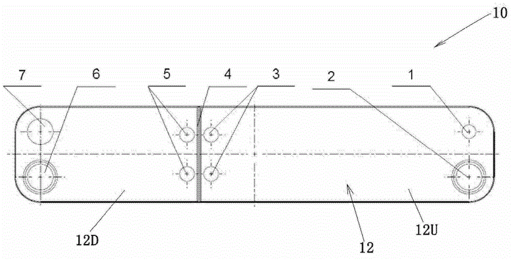
[0042] see Figure 1 to Figure 8 , The plate heat exchanger 100 according to the embodiment of the present invention includes: a heat exchange plate 10 and end plates 11 and 13 forming a first fluid channel 12 and a second fluid channel. End plates 11 and 13 are arranged on the outer sides of the heat exchange plate 10 .

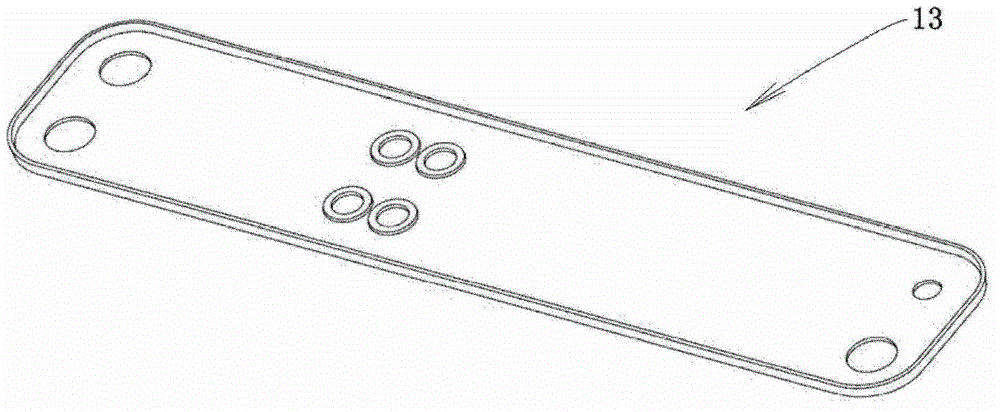
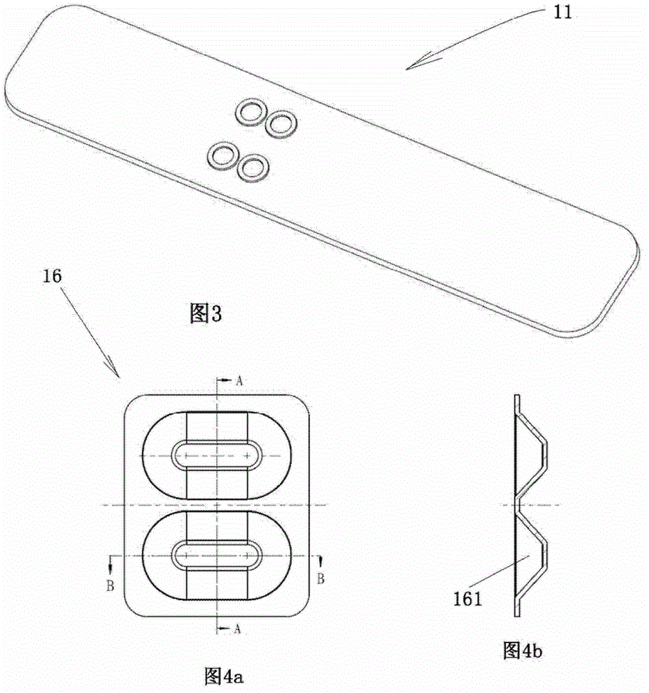
[0043] Such as figure 2 and 3 As shown, the end plates 11 and 13 respectively have the same through holes as the sides of the corresponding heat exchange plate 10 . The heat exchange plate 10 may be integrated. The plate heat exchanger 100 further comprises: a first fluid inlet 1 , a first fluid outlet 7 , a second fluid outlet 2 (for the counter-flow evaporator) and a second fluid inlet 6 (for the counter-flow evaporator). A first fluid, such as refrigerant, flows in the first fluid passage 12, and a second fluid, such as water, flows in the second fluid passage. The aperture of the first fluid inlet 1 may be smaller than the aperture of the first flu...

Embodiment 2

[0062] Such as Figure 9 and 10 As shown, for a wide plate heat exchanger 100 with a small aspect ratio, rectangular flow holes or multiple flow holes can also be used to realize the communication and mixing of the upstream area and the downstream area, such as Figure 9 and Figure 10 shown. That is, the outlet 3 of the first fluid passage upstream portion 12U and the inlet 5 of the first fluid passage downstream portion 12D have a substantially rectangular shape or the plate heat exchanger 100 has a plurality of outlets 3 of the first fluid passage upstream portion 12U and a plurality of second fluid passages. An inlet 5 of the downstream portion 12D of the fluid passage.

Embodiment 3

[0064] The present invention is also applicable to dual circle evaporators. Figure 11 is a schematic diagram of a dual-flow path refrigerant plate heat exchanger 100 . The plate heat exchanger 100 has two refrigerant circulation loops, both of which share a water circulation system for heating. Figure 11 Among them, W represents the circuit of water, R1 represents the circuit of the first refrigerant, and R2 represents the circuit of the second refrigerant. The present invention's solution to this type of application is as Figure 12 As shown, for the unilateral flow channel, 1 is the inlet of the first refrigerant (the first fluid inlet), 3 and 5 are the upstream and downstream communication plate holes (the outlet of the upstream part of the first fluid channel 12U and the first fluid channel) 1' is the inlet of the second refrigerant (first fluid inlet), 3 and 5 are its upstream and The downstream connecting plate hole (the outlet of the upstream part 12U of the first ...


PUM


Abstract

The invention provides a plate type heat exchanger. The plate type heat exchanger comprises heat exchange plates defining first fluid passages and second fluid passages, and moreover, the first fluid passage is provided with an upstream fluid passage part and a downstream fluid passage part, which communicate with each other through a fluid communicator. The plate type heat exchanger can uniformly distribute refrigerant without depending on a distributor, and moreover, based on the related heat transfer mechanism of refrigerant evaporation, different heat exchange areas are arranged in the passage in order to enhance heat transfer. Not only is the difficulty in the production and machining of the distributor-less heat exchanger based on the invention decreased, but also the practical application range and conditions of the product are broadened. In addition, since the heat exchanger does not have the distributor, the overall pressure drop of the refrigerant flow path of the heat exchanger is lower than the overall pressure drops of the refrigerant flow paths of other products, and thereby therefore more space can be reserved for the model selectionchoice of expansion valves.

Description

technical field [0001] The invention relates to a plate heat exchanger. Background technique [0002] For parallel-channel heat exchangers (evaporators), especially plate heat exchangers and micro-channel heat exchangers, refrigerant mal-distribution is a worldwide technical problem. Usually, the refrigerant entering the heat exchanger exists in the form of two phases. Due to the application conditions and the complexity of the two-phase flow, it is difficult to achieve uniform distribution of the refrigerant. In many cases, excess liquid refrigerant will flow into some channels, while too much gaseous refrigerant will flow into other channels, which will greatly affect the overall performance of the evaporator. [0003] The refrigerant distribution scheme of the existing products is realized based on the distributor technology. Common means are: diversion tube, diversion ring, embedded distributor, etc. The main idea is to set a small flow section at the entrance of each...

Claims


Application Information

Patent Timeline
Patent Type & Authority Applications(China)
IPC IPC(8): F25B39/02F25B39/00
CPCF28F3/08F28D9/00F28D9/005F28D9/0093F28F9/026F28F9/22F28F13/06F28D9/0037F28D9/0056F28F3/02F28F9/001F28D9/0043F28F3/086F25C1/12F28D7/0066
Inventor 拉尔斯·佩尔松
Owner DANFOSS HANGZHOU PLATE HEAT EXCHANGER
Why Eureka
Try Eureka